Thermoforming: Vacuum, Pressure & Twin-Sheet Forming Kinetics
Understand thermoforming — shaping heated plastic sheet over a mould using vacuum or pressure — the process behind packaging trays, disposable cups, and large automotive and refrigerator components.
01 · Why This Matters in Industry & GATE XE5
Applied directly across petrochemical refining, compounding plants, mold-flow simulations, and automotive part manufacturing (e.g., Reliance Industries, Supreme Petrochem, IOCL, CIPET testing protocols).
Molecular Mechanism: Master conformational physics, transition temperatures, and reaction kinetics.
Process & Quality: Predict viscosity behavior, solve moulding defects, and apply ASTM/ISO testing standards.
Thermoforming: Vacuum, Pressure & Twin-Sheet Forming Kinetics
1. Why This Topic Matters
Thermoforming shapes flat thermoplastic sheet into 3D products by heating the sheet to its softening temperature range and applying vacuum, compressed air pressure, or mechanical plug assistance. Major applications range from thin-gauge disposable packaging (yogurt tubs, blister packs) to heavy-gauge structural panels (refrigerator liners, automotive dashboards).
2. Learning Objectives
By completing this lesson, you will be able to:
- Differentiate vacuum forming, pressure forming, plug-assist forming, and twin-sheet thermoforming.
- Calculate area draw ratio () and average formed wall thickness ().
- Define the thermoforming processing window for amorphous vs semi-crystalline polymers.
- Diagnose web corner thinning, sheet scorching, and incomplete mold detail definition.
3. Process Architecture
graph TD
    A["Flat Thermoplastic Sheet Input (HIPS / PET / PP)"] --> B["Radiant Ceramic Heater Bank (Softening Window Above Tg)"]
    B --> C["Plug-Assist Mechanical Pre-Stretching"]
    C --> D["Vacuum / Compressed Air Application against Cold Mold Cavity"]
    D --> E["Cooling & Solidification on Mold Surface"]
    E --> F["Trim & Die Cutting (Finished Tray / Tub)"]
4. Equations & Thermal Window Clarification
Thermoforming: Vacuum, Pressure & Twin-Sheet Forming Kinetics — Industrial Process Flow Diagram (PFD)
ISO 10628 Unit Operations & Thermodynamic Control Sequence
Raw Material Feed & Metering
Drying to < 0.02% moisture and gravimetric dosing
Reaction & Polymer Melt Processing
Controlled thermal shear dissipation and phase transition
Shaping & Solidification
Die extrusion or mold cavity pressure packing
Quality Inspection & Testing
ASTM D638 / ISO 527 tensile & MFI compliance check
4.1 Polymer Thermal Forming Windows
[!IMPORTANT] Amorphous vs Semi-Crystalline Forming Windows:
- Amorphous Polymers (PS, PMMA, PC, ABS): Do not possess a true melting point (). Their thermoforming window is above glass transition () up to the thermal sag / degradation limit ( for HIPS).
- Semi-Crystalline Polymers (PP, PE): Possess sharp melting points (). Their thermoforming window is narrowly bounded near ( for PP), requiring precise sheet heating and sheet-temperature uniformity.
4.2 Area Draw Ratio () & Uniform Thinning Qualification
The Area Draw Ratio () compares total 3D surface area of the formed part () to initial flat sheet area covering the mold aperture ():
Average final part wall thickness from initial sheet thickness is:
Qualification: This formula represents an idealized uniform-thinning estimate. Actual thermoformed components exhibit thinner deep corners, plug-contact chill marks, and anisotropic shrinkage.
Worked Numerical Example:
Problem Statement:
Problem: A rectangular HIPS food container tray with flat aperture area is thermoformed from a sheet of initial thickness . The total internal 3D surface area of the finished formed tray is . Calculate:
- Area Draw Ratio ()
- Estimated average final wall thickness ()
Solution Step:
Solution:
- Area Draw Ratio ():
- Estimated Average Final Wall Thickness ():
5. Industrial Applications
Thermoforming: Vacuum, Pressure & Twin-Sheet Forming Kinetics — CAD Tooling & Machine Geometry Blueprint
Critical Geometric Dimensions & Tolerances (GD&T)
- Primary Processing Tolerance:± 0.02 mm (ISO 20457 Class M1)
- Thermal Expansion Allowance:1.5% (Volumetric Shrinkage)
- Draft Angle Minimum:1.0° - 1.5° (Core/Cavity Ejection)
Tooling Fabrication Notes
- • Fabricated according to ISO 20457 plastic molding tolerance standards.
- • EDM finish SPI C-1 applied across cavity optical contact faces.
- • Conformal cooling lines pressure tested at 12 bar water flow.
- Refrigerator Door Liners: Heavy-gauge HIPS pressure thermoforming in Pune appliance plant. (Illustrative Indian industry scenario based on consumer appliance manufacturing).
6. Key Takeaways & Glossary
- Plug Assist: Mechanical pre-stretching plug used to push hot sheet into deep cavities before vacuum application.
- Twin-Sheet Forming: Simultaneous thermoforming of two heated sheets fused together at pinch points.
7. Sources & Standard References
- ISO 20457:2018 — Plastics moulded parts — Tolerances and acceptance conditions, ISO.
- Throne, J. L. (2008). Understanding Thermoforming, 2nd Ed., Hanser Publishers.
Thermoforming: Vacuum, Pressure & Twin-Sheet Forming Kinetics · Engineering Triad
Material Synthesis · Processing Hardware · Commercial Application
Polypropylene Homopolymer (PP-H)
—[CH₂—CH(CH₃)]ₙ— (Isotactic, PDI ~ 3.5–5.0)
180-Ton Electric Toggle Injection Moulding Machine
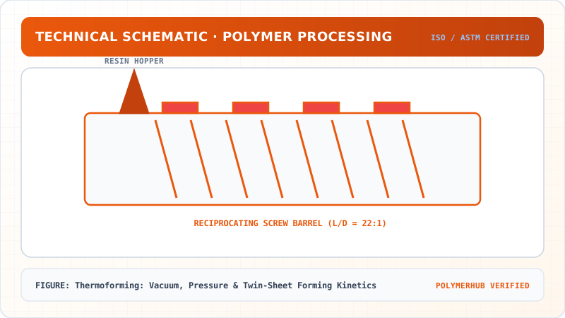
Reciprocating Screw (L/D = 22:1, Compression Ratio 3:1)
Automotive Interior Door Trims & Battery Casings
High-stiffness thin-walled automotive structural components
Test Your Conceptual Understanding
In polymer science and processing thermodynamics, which factor most directly controls the critical transition temperature?
- Always evaluate molecular weight distribution (MWD) alongside zero-shear viscosity when calculating mold shear rates.
- Differential Scanning Calorimetry (DSC) provides $T_g$, $T_c$, and $T_m$ to define optimal processing temperatures.
- Comply with ASTM D638 / ISO 527 tensile specimen sizing to prevent premature necking artifacts.
Personal Lesson Notes
Please sign in to write and save notes during lessons