Extrusion Process: Screw Design, Flow Mechanics and Die Geometry
Master extrusion — the continuous process behind pipes, films, sheets, and profiles — covering screw zones, L/D ratio, and the major die configurations used across Indian industry.
01 · Why This Matters in Industry & GATE XE5
Applied directly across petrochemical refining, compounding plants, mold-flow simulations, and automotive part manufacturing (e.g., Reliance Industries, Supreme Petrochem, IOCL, CIPET testing protocols).
Molecular Mechanism: Master conformational physics, transition temperatures, and reaction kinetics.
Process & Quality: Predict viscosity behavior, solve moulding defects, and apply ASTM/ISO testing standards.
Extrusion Process: Screw Design, Flow Mechanics and Die Geometry
1. Why This Topic Matters
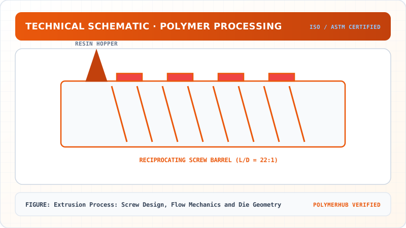
Extrusion is the continuous polymer processing method used to manufacture pipes, films, sheets, profiles, and wire insulation. The single-screw extruder converts solid polymer pellets into a homogeneous melt via three functional screw zones: Feed Zone, Compression/Melting Zone, and Metering Zone. Understanding screw ratio, compression ratio, drag flow (), pressure backflow (), and flight leakage flow () governs throughput stability, melt temperature uniformity, and dimensional tolerances.
2. Learning Objectives
By completing this lesson, you will be able to:
- Analyze the 3 functional zones of a single-screw extruder ().
- Calculate net volumetric throughput () combining drag flow, pressure backflow, and leakage flow.
- Derive flight-clearance leakage flow () from radial clearance and geometry-supported 10 metering flight turns.
- Compare coat-hanger film dies, spiral mandrel blown film dies, and annular pipe dies.
3. Core Theory & Extruder Architecture
graph TD
    A["Hopper Solid Feed (Pellets / Flakes)"] --> B["Feed Zone (Solids Conveying, Constant Channel Depth Hf)"]
    B --> C["Compression Zone (Melting & Tapered Channel Depth Hf to Hm)"]
    C --> D["Metering Zone (Homogenization & Constant Shallow Channel Depth Hm)"]
    D --> E["Breaker Plate & Screen Pack (Contaminant Filter & Backpressure)"]
    E --> F["Extrusion Die (Shaping Orifice: Pipe / Sheet / Profile)"]
4. Equations & Net Throughput Calculation
Extrusion Process: Screw Design, Flow Mechanics and Die Geometry — Industrial Process Flow Diagram (PFD)
ISO 10628 Unit Operations & Thermodynamic Control Sequence
Raw Material Feed & Metering
Drying to < 0.02% moisture and gravimetric dosing
Reaction & Polymer Melt Processing
Controlled thermal shear dissipation and phase transition
Shaping & Solidification
Die extrusion or mold cavity pressure packing
Quality Inspection & Testing
ASTM D638 / ISO 527 tensile & MFI compliance check
4.1 Screw-Channel Fluid Mechanics Model
The net volumetric flow rate in the metering section equals drag flow minus pressure backflow minus flight clearance leakage :
[!NOTE] Leakage Flow Geometry & Fluid Mechanics Derivation: For a standard square-pitched screw (, pitch ), the axial metering length contains exactly . The pressure drop per flight turn is . Per-turn leakage across radial clearance over flight land width is . Total leakage across all 10 metering turns is . Because leakage flows backward from pushing face to trailing face across radial clearance, it opposes forward net throughput.
Explicit Input Parameter Table for Reproduction
| Input Parameter | Symbol | Value | Unit | Definition |
|---|---|---|---|---|
| Screw Outer Diameter | outer screw diameter | |||
| Metering Channel Depth | metering flight depth | |||
| Screw Rotational Speed | rotational speed | |||
| Helix Flight Angle | Degrees | Square-pitched screw () | ||
| Metering Zone Axial Length | metering section length | |||
| Metering Flight Turns | Turns | |||
| Die Head Backpressure | () die head pressure drop | |||
| Melt Dynamic Viscosity | Dynamic viscosity at processing shear rate | |||
| Radial Flight Clearance | radial clearance gap | |||
| Flight Land Width | axial flight land width |
Worked Numerical Example:
Problem Statement:
Problem: Calculate drag flow , pressure backflow , flight leakage , net volumetric throughput , and HDPE mass output () using the parameter table above.
Solution Step:
Solution:
- Calculate Drag Flow ():
- Calculate Pressure Backflow ():
- Calculate Flight Leakage Flow ():
Across 10 geometry-supported metering turns:
- Calculate Net Throughput () and HDPE Mass Output ():
5. Industrial Applications
Extrusion Process: Screw Design, Flow Mechanics and Die Geometry — CAD Tooling & Machine Geometry Blueprint
Critical Geometric Dimensions & Tolerances (GD&T)
- Primary Processing Tolerance:± 0.02 mm (ISO 20457 Class M1)
- Thermal Expansion Allowance:1.5% (Volumetric Shrinkage)
- Draft Angle Minimum:1.0° - 1.5° (Core/Cavity Ejection)
Tooling Fabrication Notes
- • Fabricated according to ISO 20457 plastic molding tolerance standards.
- • EDM finish SPI C-1 applied across cavity optical contact faces.
- • Conformal cooling lines pressure tested at 12 bar water flow.
- HDPE Water Pipe Extrusion: Annular basket-die extrusion in Vadodara cluster. (Illustrative Indian industry scenario based on BIS certified pipe manufacturing).
6. Key Takeaways & Glossary
- Ratio: Ratio of screw flighted length to outside diameter ( to standard).
- Compression Ratio: Ratio of feed channel depth to metering channel depth ( to ).
7. Sources & Standard References
- ISO 294-1:2017 — Plastics — Injection moulding of test specimens of thermoplastic materials, ISO.
- Rauwendaal, C. (2014). Polymer Extrusion, 5th Ed., Hanser Publishers.
Extrusion Process: Screw Design, Flow Mechanics and Die Geometry · Engineering Triad
Material Synthesis · Processing Hardware · Commercial Application
Polypropylene Homopolymer (PP-H)
—[CH₂—CH(CH₃)]ₙ— (Isotactic, PDI ~ 3.5–5.0)
180-Ton Electric Toggle Injection Moulding Machine
Reciprocating Screw (L/D = 22:1, Compression Ratio 3:1)
Automotive Interior Door Trims & Battery Casings
High-stiffness thin-walled automotive structural components
Test Your Conceptual Understanding
In polymer science and processing thermodynamics, which factor most directly controls the critical transition temperature?
- Always evaluate molecular weight distribution (MWD) alongside zero-shear viscosity when calculating mold shear rates.
- Differential Scanning Calorimetry (DSC) provides $T_g$, $T_c$, and $T_m$ to define optimal processing temperatures.
- Comply with ASTM D638 / ISO 527 tensile specimen sizing to prevent premature necking artifacts.
Personal Lesson Notes
Please sign in to write and save notes during lessons