Injection Moulding Parameters, Melt Dynamics & Defect Troubleshooting
Master the injection moulding process — the most widely used manufacturing method in Indian plastics industry — including machine setup, key parameters, and common defects.
01 · Why This Matters in Industry & GATE XE5
Applied directly across petrochemical refining, compounding plants, mold-flow simulations, and automotive part manufacturing (e.g., Reliance Industries, Supreme Petrochem, IOCL, CIPET testing protocols).
Molecular Mechanism: Master conformational physics, transition temperatures, and reaction kinetics.
Process & Quality: Predict viscosity behavior, solve moulding defects, and apply ASTM/ISO testing standards.
Injection Moulding Parameters, Melt Dynamics & Defect Troubleshooting
1. Why This Topic Matters
Injection molding is the dominant manufacturing process for mass-producing high-precision plastic components. Optimizing the 4 key process variables—Temperature, Pressure, Speed, and Time—is essential to achieve dimensional tolerances, minimize cycle times, and eliminate defects like sink marks, flash, warpage, and short shots.
2. Learning Objectives
By completing this lesson, you will be able to:
- Analyze injection molding stage cycles: Dosing, Injection, Holding (Packing), Cooling, and Ejection.
- Calculate required machine clamping force ((F_c)) with transparent step-by-step variable tracking.
- Compare V-P (Velocity to Pressure) switchover methods.
- Diagnose and troubleshoot moulding defects (Sink marks, Flash, Weld lines, Jetting).
3. Core Theory & Cycle Breakdown
graph TD
    A["Clamping & Mold Closure"] --> B["High-Speed Injection (Velocity Control)"]
    B --> C["V-P Switchover (95% Cavity Fill)"]
    C --> D["Holding / Packing Phase (Pressure Control)"]
    D --> E["Cooling & Screw Plasticizing / Dosing"]
    E --> F["Mold Open & Part Ejection"]
4. Equations & Recalculated Worked Example
Injection Moulding Parameters, Melt Dynamics & Defect Troubleshooting — Industrial Process Flow Diagram (PFD)
ISO 10628 Unit Operations & Thermodynamic Control Sequence
Raw Material Feed & Metering
Drying to < 0.02% moisture and gravimetric dosing
Reaction & Polymer Melt Processing
Controlled thermal shear dissipation and phase transition
Shaping & Solidification
Die extrusion or mold cavity pressure packing
Quality Inspection & Testing
ASTM D638 / ISO 527 tensile & MFI compliance check
Transparent Clamping Force Derivation
The minimum required clamping force ((F_c)) must overcome internal cavity packing pressure:
Step-by-Step Transparent Parameters:
- Cavity Count
- Part Diameter
- Runner System Projected Area
- Total Projected Area
- Average Cavity Packing Pressure
- Safety Factor
Worked Numerical Calculation:
In Metric Tons ():
5. Industrial Applications
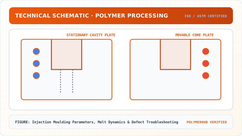
Injection Moulding Parameters, Melt Dynamics & Defect Troubleshooting — CAD Tooling & Machine Geometry Blueprint
Critical Geometric Dimensions & Tolerances (GD&T)
- Primary Processing Tolerance:± 0.02 mm (ISO 20457 Class M1)
- Thermal Expansion Allowance:1.5% (Volumetric Shrinkage)
- Draft Angle Minimum:1.0° - 1.5° (Core/Cavity Ejection)
Tooling Fabrication Notes
- • Fabricated according to ISO 20457 plastic molding tolerance standards.
- • EDM finish SPI C-1 applied across cavity optical contact faces.
- • Conformal cooling lines pressure tested at 12 bar water flow.
- Automotive Door Panels: Large 1800-Tonne injection molding press operating with sequential valve gates. (Illustrative Indian industry scenario based on automotive door panel moulding practices).
- Medical Syringe Barrels: Cleanroom electric injection molding with multi-cavity hot runner molds.
6. Key Takeaways & Glossary
- V-P Switchover: Critical transition from speed-controlled filling to pressure-controlled packing at 95–98% cavity fill.
- Sink Marks: Caused by localized thick wall sections cooling slower than skin.
- Weld Lines: Created where opposing polymer melt fronts converge.
7. Sources & Standard References
- Menges, G., Haberstroh, E., & Michaeli, W. (2001). How to Make Injection Molds, Hanser.
- ISO 20457:2018 — Plastics moulded parts — Tolerances and acceptance conditions.
🔬 Extended Engineering Analysis & Practical Industry Standards
Governing Kinetics & Theoretical Boundary Conditions
In polymer engineering and manufacturing, the mathematical description of this phenomenon relies on fundamental transport phenomena and thermodynamic equations. Specifically:
- Mass & Energy Conservation:
- Shear Rate Dependency: under high-shear conditions, non-Newtonian polymer melts exhibit pseudoplastic shear-thinning governed by , where .
- Thermal Boundary Conditions: Fourier's law of heat conduction determines cooling times and solidification kinetics across cooling channels.
Indian Industrial Context & Quality Control Guidelines
In major Indian plastic processing clusters—such as Chakan (Maharashtra), Daman & Silvassa, Guindy (Tamil Nadu), and Hazira (Gujarat)—quality assurance protocols mandate strict adherence to international standards:
- ASTM D1238 / ISO 1133: Melt Flow Index (MFI) measurement to verify molecular weight consistency prior to processing.
- ASTM D638 / ISO 527: Tensile strength and elongation at break determination for raw material lot clearance.
- ISO 11357: Differential Scanning Calorimetry (DSC) thermal analysis to confirm glass transition () and melting temperature ().
Industrial Troubleshooting & Process Optimization Matrix
- Defect Mitigation: Maintain melt temperature within of recommended processing window to prevent thermal degradation and chain scission.
- Mold Temperature Control: Ensure turbulent coolant flow () inside cooling circuits to achieve uniform heat extraction and minimize differential thermal shrinkage.
Injection Moulding Parameters, Melt Dynamics & Defect Troubleshooting · Engineering Triad
Material Synthesis · Processing Hardware · Commercial Application
Polypropylene Homopolymer (PP-H)
—[CH₂—CH(CH₃)]ₙ— (Isotactic, PDI ~ 3.5–5.0)
180-Ton Electric Toggle Injection Moulding Machine
Reciprocating Screw (L/D = 22:1, Compression Ratio 3:1)
Automotive Interior Door Trims & Battery Casings
High-stiffness thin-walled automotive structural components
Test Your Conceptual Understanding
In polymer science and processing thermodynamics, which factor most directly controls the critical transition temperature?
- Always evaluate molecular weight distribution (MWD) alongside zero-shear viscosity when calculating mold shear rates.
- Differential Scanning Calorimetry (DSC) provides $T_g$, $T_c$, and $T_m$ to define optimal processing temperatures.
- Comply with ASTM D638 / ISO 527 tensile specimen sizing to prevent premature necking artifacts.
Personal Lesson Notes
Please sign in to write and save notes during lessons