Compression and Transfer Moulding of Thermosetting Polymers
Learn the two primary processes for moulding thermoset materials — compression moulding and transfer moulding — and why these differ fundamentally from thermoplastic processing.
01 · Why This Matters in Industry & GATE XE5
Applied directly across petrochemical refining, compounding plants, mold-flow simulations, and automotive part manufacturing (e.g., Reliance Industries, Supreme Petrochem, IOCL, CIPET testing protocols).
Molecular Mechanism: Master conformational physics, transition temperatures, and reaction kinetics.
Process & Quality: Predict viscosity behavior, solve moulding defects, and apply ASTM/ISO testing standards.
Compression and Transfer Moulding of Thermosetting Polymers
1. Why This Topic Matters
Compression and transfer moulding are the primary manufacturing processes for crosslinked thermosetting resins (Phenol-Formaldehyde, Melamine-Formaldehyde, Epoxy, and Unsaturated Polyester BMC/SMC). Unlike thermoplastics, thermosets undergo an irreversible exothermic chemical crosslinking reaction (curing) inside the heated mold cavity (). These processes are vital for producing high-temperature electrical switchgear, automotive brake pads, circuit breakers, and structural composite panels.
2. Learning Objectives
By completing this lesson, you will be able to:
- Differentiate compression moulding from pot transfer moulding mechanisms.
- Calculate transfer pot ram pressure, clamping force (), and cure time using the Gel-Time equation.
- Compare flash, positive, and semi-positive compression mold designs.
- Diagnose blistering, gas entrapment, and under-cure in thick-walled thermoset moldings.
3. Core Theory & Process Comparison
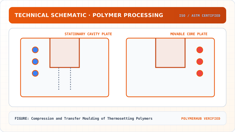
3.1 Compression Moulding Sequence
Pre-formed or powdered charge is placed directly into an open, heated cavity. The upper mold half descends, compressing the resin, forcing it into cavity contours while activating thermal crosslinking.
3.2 Transfer Moulding Mechanics
Thermoset charge is pre-heated in a separate transfer pot and injected through sprue and runners into the closed mold cavity by a hydraulic ram, yielding superior dimensional accuracy and minimal parting line flash.
graph TD
    A["Pre-heated Charge Placement in Pot / Cavity"] --> B["Hydraulic Ram Descent & Pressure Application"]
    B --> C["Resin Liquefaction & Cavity Flow"]
    C --> D["Exothermic Chemical Crosslinking (Cure Phase)"]
    D --> E["Mold Opening & Hot Ejection of Cured Component"]
4. Equations & Recalculated Worked Example
Compression and Transfer Moulding of Thermosetting Polymers — Industrial Process Flow Diagram (PFD)
ISO 10628 Unit Operations & Thermodynamic Control Sequence
Raw Material Feed & Metering
Drying to < 0.02% moisture and gravimetric dosing
Reaction & Polymer Melt Processing
Controlled thermal shear dissipation and phase transition
Shaping & Solidification
Die extrusion or mold cavity pressure packing
Quality Inspection & Testing
ASTM D638 / ISO 527 tensile & MFI compliance check
Transfer Pot Pressure & Hydraulic Clamping Force
The required press clamping force () must exceed the total separation force exerted by transfer pot pressure () across cavity projected areas:
Where .
Worked Numerical Example:
Problem Statement:
Problem: A 4-cavity transfer mold produces phenolic resin electrical switch housings. Each housing has a projected area . The runner system contributes an additional . The transfer pot ram exerts a hydraulic fluid pressure (). Using a safety factor , calculate the required hydraulic press clamping tonnage.
Solution Step:
Solution:
- Calculate total projected area ():
- Calculate Clamping Force ():
- Convert to Metric Tonnage ():
5. Industrial Applications
Compression and Transfer Moulding of Thermosetting Polymers — CAD Tooling & Machine Geometry Blueprint
Critical Geometric Dimensions & Tolerances (GD&T)
- Primary Processing Tolerance:± 0.02 mm (ISO 20457 Class M1)
- Thermal Expansion Allowance:1.5% (Volumetric Shrinkage)
- Draft Angle Minimum:1.0° - 1.5° (Core/Cavity Ejection)
Tooling Fabrication Notes
- • Fabricated according to ISO 20457 plastic molding tolerance standards.
- • EDM finish SPI C-1 applied across cavity optical contact faces.
- • Conformal cooling lines pressure tested at 12 bar water flow.
- Electrical Switchgear: Phenolic (Bakelite) circuit breaker housings moulded on 100-Tonne transfer presses. (Illustrative Indian industry scenario based on electrical equipment manufacturing hubs in Mumbai/Pune).
- Automotive Brake Pads: Friction material compression moulding using phenolic binder resin under high tonnage.
6. Key Takeaways & Glossary
- Crosslinking / Curing: Irreversible 3D covalent network formation driven by heat.
- Transfer Pot: Chamber where charge is plasticized before hydraulic injection into closed cavity.
- Breathe Cycle: Momentary mold opening during initial compression to release trapped moisture and volatiles.
7. Sources & Standard References
- Strong, A. B. (2005). Plastics: Materials and Processing, 3rd Ed., Pearson.
- ISO 295:2004 — Plastics — Compression moulding of test specimens of thermosetting materials.
Compression and Transfer Moulding of Thermosetting Polymers · Engineering Triad
Material Synthesis · Processing Hardware · Commercial Application
Polypropylene Homopolymer (PP-H)
—[CH₂—CH(CH₃)]ₙ— (Isotactic, PDI ~ 3.5–5.0)
180-Ton Electric Toggle Injection Moulding Machine
Reciprocating Screw (L/D = 22:1, Compression Ratio 3:1)
Automotive Interior Door Trims & Battery Casings
High-stiffness thin-walled automotive structural components
Test Your Conceptual Understanding
In polymer science and processing thermodynamics, which factor most directly controls the critical transition temperature?
- Always evaluate molecular weight distribution (MWD) alongside zero-shear viscosity when calculating mold shear rates.
- Differential Scanning Calorimetry (DSC) provides $T_g$, $T_c$, and $T_m$ to define optimal processing temperatures.
- Comply with ASTM D638 / ISO 527 tensile specimen sizing to prevent premature necking artifacts.
Personal Lesson Notes
Please sign in to write and save notes during lessons