Microcellular Foam Injection Moulding (MuCell): Supercritical Fluid Physics & Nucleation
Microcellular foam injection moulding, Supercritical Fluid (SCF N2/CO2) single-phase solution, thermodynamic cell nucleation, cell density, weight reduction, and sink mark elimination.
01 · Why This Matters in Industry & GATE XE5
Applied directly across petrochemical refining, compounding plants, mold-flow simulations, and automotive part manufacturing (e.g., Reliance Industries, Supreme Petrochem, IOCL, CIPET testing protocols).
Molecular Mechanism: Master conformational physics, transition temperatures, and reaction kinetics.
Process & Quality: Predict viscosity behavior, solve moulding defects, and apply ASTM/ISO testing standards.
Microcellular Foam Injection Moulding (MuCell): Supercritical Fluid Physics & Nucleation
1. Why This Topic Matters
Microcellular foam injection moulding (commercialised as the MuCell® process) represents a major shift in lightweight plastic design. By injecting a supercritical fluid (SCF, typically or ) into the polymer melt, it creates a single-phase solution. Upon injection into the cavity, the sudden pressure drop triggers thermodynamic instability, nucleating billions of micro-scale cells ( m). This process reduces part weight by 10–20%, eliminates sink marks, and lowers clamp force requirements. Indian automotive suppliers (e.g., Motherson Sumi, Tata AutoComp) use MuCell to manufacture lightweight dashboard structures and engine shrouds.
2. Learning Objectives
- Explain the phase diagram of supercritical fluids () and how they act as physical blowing agents.
- Detail the thermodynamic process of single-phase melt-SCF solution formation in the extruder barrel.
- Analyze cell nucleation kinetics using classical nucleation theory equations.
- Compare microcellular foam properties with conventional chemical blowing agents.
- Reference microcellular foam standards and processing guidelines.
3. Core Theory
3.1 Supercritical Fluids as Blowing Agents
A fluid is supercritical when its temperature and pressure exceed its critical point ():
- : C, MPa. Preferred for injection moulding due to low solubility and high cell density.
- : C, MPa. Higher solubility; used for foaming soft polymers (TPUs, elastomers). In the supercritical state, they have gas-like diffusivity and liquid-like density, allowing rapid dissolution into the polymer melt.
3.2 Single-Phase Solution and Viscosity Reduction
The SCF is metered and injected directly into the extruder barrel at high pressure. Specialized mixing screw elements dissolve the SCF into the melt to form a single-phase solution:
- Plasticisation: Dissolved SCF molecules screen polymer chain interactions, acting as a temporary plasticiser.
- Viscosity Drop: The melt viscosity decreases by 20–40%, permitting lower processing temperatures and lower injection pressures.
3.3 Cell Nucleation Kinetics (Thermodynamic Instability)
When the solution is injected through the gate, it experiences a rapid pressure drop rate ( GPa/s). This triggers thermodynamic instability, reducing SCF solubility and causing phase separation. The homogeneous nucleation rate () of cells is:
Where:
- : Frequency factor of gas molecules joining the nucleus
- : Concentration of gas in the solution
- : Boltzmann constant
- : Critical Gibbs free energy barrier for nucleation:
Where is the surface energy of the polymer-gas interface, and is the pressure drop magnitude.
4. Worked Example
Microcellular Foam Injection Moulding (MuCell): Supercritical Fluid Physics & Nucleation — Industrial Process Flow Diagram (PFD)
ISO 10628 Unit Operations & Thermodynamic Control Sequence
Raw Material Feed & Metering
Drying to < 0.02% moisture and gravimetric dosing
Reaction & Polymer Melt Processing
Controlled thermal shear dissipation and phase transition
Shaping & Solidification
Die extrusion or mold cavity pressure packing
Quality Inspection & Testing
ASTM D638 / ISO 527 tensile & MFI compliance check
Problem Statement:
Problem: A MuCell injection moulding process uses nitrogen () as the SCF in a PP melt. The pressure drop at the gate during injection is MPa. The surface energy of the PP- interface is J/m². Calculate the critical free energy barrier () for homogeneous cell nucleation.
Solution Step:
Solution:
- Express variables in standard SI units:
- J/m²
- Pa
- Calculate :
Interpretation: The energy barrier for homogeneous cell nucleation is Joules. To increase the cell nucleation rate () and achieve smaller cell sizes, the engineer must increase the pressure drop rate () at the gate, which effectively increases , lowering .
5. Indian Industry Context
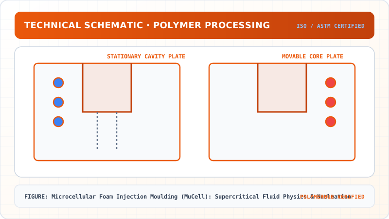
Microcellular Foam Injection Moulding (MuCell): Supercritical Fluid Physics & Nucleation — CAD Tooling & Machine Geometry Blueprint
Critical Geometric Dimensions & Tolerances (GD&T)
- Primary Processing Tolerance:± 0.02 mm (ISO 20457 Class M1)
- Thermal Expansion Allowance:1.5% (Volumetric Shrinkage)
- Draft Angle Minimum:1.0° - 1.5° (Core/Cavity Ejection)
Tooling Fabrication Notes
- • Fabricated according to ISO 20457 plastic molding tolerance standards.
- • EDM finish SPI C-1 applied across cavity optical contact faces.
- • Conformal cooling lines pressure tested at 12 bar water flow.
Tata AutoComp Systems (Pune) utilizes MuCell technology in their automotive interior business unit. They manufacture lightweight door trims and instrument panel carriers for Tata Motors passenger vehicles (e.g., Nexon, Harrier), saving 12% in component weight while eliminating sink marks on structural ribs.
Motherson Automotive uses microcellular injection moulding for dashboard structures. They adjust the SCF dosage (typically 0.3 wt% ) to prevent cell coalescence and structural skin thickness variation.
6. Key Takeaways & Glossary
- MuCell: Physical foaming process using supercritical nitrogen or carbon dioxide.
- Single-Phase Solution: Uniform mixture where gas molecules are dissolved in the polymer matrix without phase boundary.
- Thermodynamic Instability: State triggered by a rapid pressure drop, driving phase separation of gas from melt.
- PIAT: (Not applicable, rotomoulding parameter).
- (Nucleation Rate): Number of gas bubbles nucleated per unit volume per unit time.
7. Standards Reference
- ASTM D785 — Standard Test Method for Rockwell Hardness of Plastics and Electrical Insulating Materials (used to qualify cell structure density)
- ISO 19095 — Plastics — Evaluation of the adhesion interface in plastic-metal assemblies (relevant to foamed insert moulding)
- VDI 2007 — Guidelines for Microcellular Injection Moulding of Thermoplastics
8. Practice Questions
- Compare physical foaming (MuCell) with chemical foaming agents (CFAs). Focus on cell size, density, and chemical residues.
- Using classical nucleation theory, explain how adding talc nanoparticles (acting as heterogeneous nucleating agents) reduces the energy barrier for bubble formation.
- Why does the MuCell process eliminate sink marks on parts with thick ribs? Describe the internal pressure dynamics during cooling.
Microcellular Foam Injection Moulding (MuCell): Supercritical Fluid Physics & Nucleation · Engineering Triad
Material Synthesis · Processing Hardware · Commercial Application
Polypropylene Homopolymer (PP-H)
—[CH₂—CH(CH₃)]ₙ— (Isotactic, PDI ~ 3.5–5.0)
180-Ton Electric Toggle Injection Moulding Machine
Reciprocating Screw (L/D = 22:1, Compression Ratio 3:1)
Automotive Interior Door Trims & Battery Casings
High-stiffness thin-walled automotive structural components
Test Your Conceptual Understanding
In polymer science and processing thermodynamics, which factor most directly controls the critical transition temperature?
- Always evaluate molecular weight distribution (MWD) alongside zero-shear viscosity when calculating mold shear rates.
- Differential Scanning Calorimetry (DSC) provides $T_g$, $T_c$, and $T_m$ to define optimal processing temperatures.
- Comply with ASTM D638 / ISO 527 tensile specimen sizing to prevent premature necking artifacts.
Personal Lesson Notes
Please sign in to write and save notes during lessons