Undercut Release Mechanics: Side Cores, Angular Cam Pins, Slides & Lifters
Mechanical tool kinematics for external and internal undercuts, angle pin stroke calculations, side slide travel, heel locking blocks, and internal lifters.
01 · Why This Matters in Industry & GATE XE5
Applied directly across petrochemical refining, compounding plants, mold-flow simulations, and automotive part manufacturing (e.g., Reliance Industries, Supreme Petrochem, IOCL, CIPET testing protocols).
Molecular Mechanism: Master conformational physics, transition temperatures, and reaction kinetics.
Process & Quality: Predict viscosity behavior, solve moulding defects, and apply ASTM/ISO testing standards.
Undercut Release Mechanics: Side Cores, Angular Cam Pins, Slides & Lifters
1. Why This Topic Matters
Plastic part designs often include features like snap-fits, side holes, internal threads, or latching mechanisms that are perpendicular to the mould-opening direction. These features, called undercuts, block the part from ejecting directly. Releasing these features without destroying the part requires mechanical mechanisms built into the injection mould. Designing slides, cam pins, and lifters is a core skill for mould designers at Indian tooling firms (e.g., Godrej Tooling, Rico Auto) to supply high-precision automotive and consumer electronics moulds.
2. Learning Objectives
- Define internal and external undercuts and identify their typical molding release solutions.
- Explain the mechanical operation of side-action slides driven by angular cam pins.
- Solve the relationship between slide travel distance, cam pin angle, and mould opening stroke.
- Design internal lifter mechanisms, analyzing the angle limits to prevent binding.
- Reference mould building guidelines and standards.
3. Core Theory
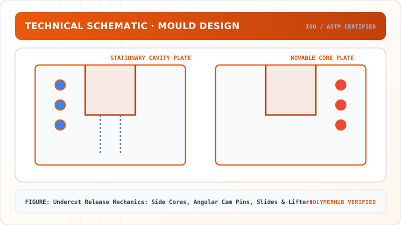
3.1 Undercuts Classifications
- External Undercuts: Located on the outer surface of the part. Released using slides (side cores) that retract outward perpendicular to the mould-open stroke.
- Internal Undercuts: Located on the interior cavities of the part (e.g., internal snaps). Released using lifters or collapsible cores that move inward and upward during ejection.
3.2 Slide Mechanics with Angular Cam Pins
A slide assembly consists of a slide body, a wear plate, an angular cam pin, and a locking block:
- Action: During mould opening, the angled cam pin (fixed to the cavity side) pulls the slide body (on the core side) outward along guided slots.
- Locking Block: Clamps the slide body in place when the mould is closed to prevent the high pressure of the plastic melt from shifting the slide.
3.3 Kinematic Equations for Cam Pin Slides
The relationship between slide travel (), mould opening stroke (), and cam pin angle (, typical range to ) is:
To prevent bending and wear of the cam pin, the angle should not exceed (usually or is preferred). The locking block angle is usually set to larger than the cam pin angle to prevent binding.
3.4 Internal Lifters
Lifters are ejector pins mounted on an angle. During ejection, as the ejector plate moves forward, the lifter slides along a guide channel, moving both forward and inward, releasing the internal undercut.
4. Worked Example
Undercut Release Mechanics: Side Cores, Angular Cam Pins, Slides & Lifters — Industrial Process Flow Diagram (PFD)
ISO 10628 Unit Operations & Thermodynamic Control Sequence
Raw Material Feed & Metering
Drying to < 0.02% moisture and gravimetric dosing
Reaction & Polymer Melt Processing
Controlled thermal shear dissipation and phase transition
Shaping & Solidification
Die extrusion or mold cavity pressure packing
Quality Inspection & Testing
ASTM D638 / ISO 527 tensile & MFI compliance check
Problem Statement:
Problem: An injection moulded housing has an external clip undercut that requires a slide travel distance mm to clear the part surface. The design uses an angular cam pin set at an angle . Calculate:
- The minimum mould-opening stroke () required to fully retract the slide.
- If the cam pin angle is reduced to to reduce shear load, calculate the new required mould stroke.
Solution Step:
Solution:
- Rearrange the slide kinematic equation to solve for at :
- Calculate for :
Interpretation: Reducing the cam pin angle to lowers the mechanical stress on the pin, but increases the required mould opening stroke from 32.97 mm to 44.78 mm. The designer must ensure that the injection molding machine has sufficient opening stroke clearance to accommodate this movement.
5. Indian Industry Context
Undercut Release Mechanics: Side Cores, Angular Cam Pins, Slides & Lifters — CAD Tooling & Machine Geometry Blueprint
Critical Geometric Dimensions & Tolerances (GD&T)
- Primary Processing Tolerance:± 0.02 mm (ISO 20457 Class M1)
- Thermal Expansion Allowance:1.5% (Volumetric Shrinkage)
- Draft Angle Minimum:1.0° - 1.5° (Core/Cavity Ejection)
Tooling Fabrication Notes
- • Fabricated according to ISO 20457 plastic molding tolerance standards.
- • EDM finish SPI C-1 applied across cavity optical contact faces.
- • Conformal cooling lines pressure tested at 12 bar water flow.
Godrej Tooling (Mumbai) designs and manufactures large multi-cavity injection moulds for automotive instrument panels and consumer washing machine tubs. They utilize Moldflow analysis and kinematic simulations to verify that slide mechanisms do not interfere with the core ejection pins during high-speed production.
Toolrooms qualify guide rail wear plates (usually fabricated from self-lubricating graphite-embedded bronze alloys) to ensure reliable operation over millions of cycles.
6. Key Takeaways & Glossary
- Undercut: Part design feature that prevents direct ejection along the mould opening axis.
- Slide (Side Core): Retractable mould insert used to release external undercuts.
- Cam Pin: Angled metal pin driving the slide body lateral movement during mould opening.
- Lifter: Angled ejector pin that moves forward and inward to release internal undercuts.
- Locking Block: High-strength block clamping the slide in place when the mould is closed.
7. Standards Reference
- HASCO Standard Component Catalog for Mould Building (industry reference)
- DME Mould Components Specifications
- ISO 12100 — Safety of machinery (principles for tool design and moving cores)
8. Practice Questions
- Contrast slides and lifters in terms of mechanical design, undercut type released, and relative tooling cost.
- Explain the purpose of setting the locking block angle to larger than the cam pin angle. What happens if they are equal?
- Sketch a section view of a slide assembly showing the cam pin, locking block, slide body, wear plates, and slide retainer springs.
Undercut Release Mechanics: Side Cores, Angular Cam Pins, Slides & Lifters · Engineering Triad
Material Synthesis · Processing Hardware · Commercial Application
Polycarbonate (PC) Optical Grade
—[O—C₆H₄—C(CH₃)₂—C₆H₄—O—CO]ₙ— (Bisphenol A Polycarbonate)
250-Ton Precision Servo-Hydraulic Moulding Machine
Optics-Calibrated Injection Compression Unit
Automotive Headlamp Lenses & Safety Visors
Impact-resistant optical enclosures with UV-stabilized coating
Test Your Conceptual Understanding
In polymer science and processing thermodynamics, which factor most directly controls the critical transition temperature?
- Always evaluate molecular weight distribution (MWD) alongside zero-shear viscosity when calculating mold shear rates.
- Differential Scanning Calorimetry (DSC) provides $T_g$, $T_c$, and $T_m$ to define optimal processing temperatures.
- Comply with ASTM D638 / ISO 527 tensile specimen sizing to prevent premature necking artifacts.
Personal Lesson Notes
Please sign in to write and save notes during lessons