Hot Runner Valve Gating Mechanics, Sequential Injection & Thermal Control
Hot runner manifold design, thermal expansion growth allowance formulas, pneumatic vs hydraulic valve pin actuation, and sequential valve gating timing for cosmetic weld-line elimination.
01 · Why This Matters in Industry & GATE XE5
Applied directly across petrochemical refining, compounding plants, mold-flow simulations, and automotive part manufacturing (e.g., Reliance Industries, Supreme Petrochem, IOCL, CIPET testing protocols).
Molecular Mechanism: Master conformational physics, transition temperatures, and reaction kinetics.
Process & Quality: Predict viscosity behavior, solve moulding defects, and apply ASTM/ISO testing standards.
Hot Runner Valve Gating Mechanics, Sequential Injection & Thermal Control
1. Why This Topic Matters
In high-volume injection moulding, hot runners eliminate runner scrap, reduce cycle time, and lower injection pressure requirements. Using valve gates allows active control of the melt flow into the cavity, enabling sequential valve gating to eliminate weld lines, control melt front advancement, and minimize clamp force. Leading Indian mould builders like Motherson Mold, Supreme Tooling, and Rico Auto utilize hot runner valve gating systems to manufacture defect-free automotive components.
2. Learning Objectives
- Compare hot runner systems with cold runners in terms of thermal stability and pressure drop.
- Detail the mechanics of pneumatic, hydraulic, and servo-driven valve gate systems.
- Design a sequential valve gating (SVG) schedule to eliminate weld lines in large parts.
- Analyze thermal control elements including PID controllers, heater bands, and thermocouple placement.
- Reference mould design standards such as ISO 294.
3. Core Theory
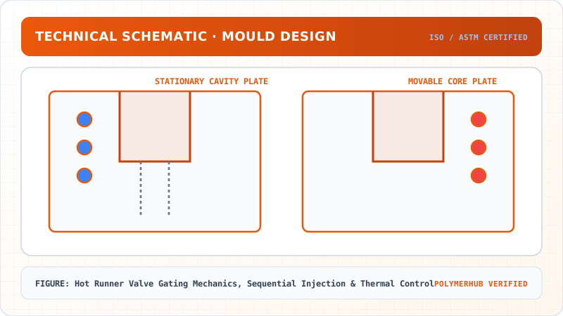
3.1 Hot Runner vs. Cold Runner Systems
Hot runners maintain the polymer melt in a molten state from the machine nozzle to the cavity gate. This eliminates the runner scrap and reduces cycle times since the runner does not need to solidify before ejection.
- Manifold Design: Internally or externally heated channels. Balanced flow channels (equal length, equal diameters) are essential to prevent pressure and temperature variations.
- Thermal Control: Requires multiple PID heat zones with closed-loop thermocouples to prevent polymer degradation or freeze-off.
3.2 Valve Gating Mechanics
Valve gates utilize a movable cylindrical pin located inside the drop nozzle to mechanically open and close the gate orifice:
- Actuation: Pneumatic (clean, cost-effective), Hydraulic (high force, compact), or Servo-electric (precise velocity and stroke control).
- Benefits: Eliminates drooling, gate vestige, and stringing. Allows large gate diameters for low shear rates.
3.3 Sequential Valve Gating (SVG)
In SVG, multiple gates feed a single cavity. The gates are opened and closed in a specific sequence based on the position of the melt front (detected via pressure sensors or time-delay calculations):
- Weld Line Elimination: By opening a secondary gate only after the melt front has passed it, weld lines (knit lines) are eliminated.
- Clamping Force Reduction: Prevents over-packing near the gates, reducing the required clamping tonnage.
4. Worked Example
Hot Runner Valve Gating Mechanics, Sequential Injection & Thermal Control — Industrial Process Flow Diagram (PFD)
ISO 10628 Unit Operations & Thermodynamic Control Sequence
Raw Material Feed & Metering
Drying to < 0.02% moisture and gravimetric dosing
Reaction & Polymer Melt Processing
Controlled thermal shear dissipation and phase transition
Shaping & Solidification
Die extrusion or mold cavity pressure packing
Quality Inspection & Testing
ASTM D638 / ISO 527 tensile & MFI compliance check
Problem Statement:
Problem: A multi-gate sequential system is designed for an automotive bumper mould with three gates: Gate 1 (centre), Gate 2 (left), and Gate 3 (right). The cavity fill rate is cm³/s. The volume from Gate 1 to Gate 2 is 360 cm³. The volume from Gate 1 to Gate 3 is 360 cm³. Calculate:
- The time delay required before opening Gate 2 and Gate 3 after Gate 1 opens.
- If the valve gate response time is 150 ms, adjust the trigger time.
Solution Step:
Solution:
- Calculate the fill time required for the melt front to reach the secondary gates:
- Adjust for the valve gate actuation response time (150 ms = 0.15 s). To ensure the gate is fully open when the melt front arrives, the trigger must be sent earlier:
Interpretation: Gate 1 opens at s. The controller must send the opening signal to the actuators of Gate 2 and Gate 3 at s so that they open at exactly s when the melt front arrives. This prevents flow hesitation and weld line formation.
5. Indian Industry Context
Hot Runner Valve Gating Mechanics, Sequential Injection & Thermal Control — CAD Tooling & Machine Geometry Blueprint
Critical Geometric Dimensions & Tolerances (GD&T)
- Primary Processing Tolerance:± 0.02 mm (ISO 20457 Class M1)
- Thermal Expansion Allowance:1.5% (Volumetric Shrinkage)
- Draft Angle Minimum:1.0° - 1.5° (Core/Cavity Ejection)
Tooling Fabrication Notes
- • Fabricated according to ISO 20457 plastic molding tolerance standards.
- • EDM finish SPI C-1 applied across cavity optical contact faces.
- • Conformal cooling lines pressure tested at 12 bar water flow.
Motherson Sumi Systems (Noida) operates injection moulding facilities producing exterior bumpers and instrument panels for passenger cars. They use hot runner valve gating systems controlled by multi-channel PID temperature controllers to maintain melt temperatures within °C, ensuring consistent part weights.
Indian toolrooms qualify hot runner systems per the hot-runner manufacturer specifications (e.g., Yudo, Mold-Masters, Synventive) matching automotive standard tests.
6. Key Takeaways & Glossary
- Valve Gate: A mechanical pin mechanism sealing the gate orifice to prevent drool.
- Sequential Valve Gating (SVG): Programmed opening of gates to control flow fronts and eliminate weld lines.
- Manifold: Heat-controlled distribution block routing polymer melt to nozzle drops.
- Drooling: Leakage of melt from gate when mould is open; eliminated by valve gating.
- PID Controller: Proportional-Integral-Derivative temperature control system minimizing overshoot.
7. Standards Reference
- ISO 294-1 — Injection moulding of test specimens of thermoplastic materials
- ASTM D3641 — Standard Practice for Injection Molding Test Specimens of Thermoplastic Molding and Extrusion Materials
- SPI Mold Design Classifications and Standards
8. Practice Questions
- Contrast thermal gating (tip freeze-off) and valve gating in terms of gate vestige quality and cycle time.
- Explain the phenomenon of "pressure drop" in hot runner manifolds and how balanced layout branches prevent pressure imbalance.
- Design a flow chart showing the sequence of signals between cavity pressure sensors and valve gate actuators during a moulding cycle.
Hot Runner Valve Gating Mechanics, Sequential Injection & Thermal Control · Engineering Triad
Material Synthesis · Processing Hardware · Commercial Application
Polycarbonate (PC) Optical Grade
—[O—C₆H₄—C(CH₃)₂—C₆H₄—O—CO]ₙ— (Bisphenol A Polycarbonate)
250-Ton Precision Servo-Hydraulic Moulding Machine
Optics-Calibrated Injection Compression Unit
Automotive Headlamp Lenses & Safety Visors
Impact-resistant optical enclosures with UV-stabilized coating
Test Your Conceptual Understanding
In polymer science and processing thermodynamics, which factor most directly controls the critical transition temperature?
- Always evaluate molecular weight distribution (MWD) alongside zero-shear viscosity when calculating mold shear rates.
- Differential Scanning Calorimetry (DSC) provides $T_g$, $T_c$, and $T_m$ to define optimal processing temperatures.
- Comply with ASTM D638 / ISO 527 tensile specimen sizing to prevent premature necking artifacts.
Personal Lesson Notes
Please sign in to write and save notes during lessons