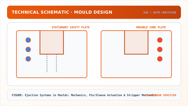
Ejection Systems in Moulds: Mechanics, Pin/Sleeve Actuation & Stripper Mechanics
Understand how moulded parts are safely removed from the mould without damage, covering ejector pin design, stripper plates, and air-assisted ejection for thin-wall and deep-draw parts.
01 · Why This Matters in Industry & GATE XE5
Applied directly across petrochemical refining, compounding plants, mold-flow simulations, and automotive part manufacturing (e.g., Reliance Industries, Supreme Petrochem, IOCL, CIPET testing protocols).
Molecular Mechanism: Master conformational physics, transition temperatures, and reaction kinetics.
Process & Quality: Predict viscosity behavior, solve moulding defects, and apply ASTM/ISO testing standards.
Ejection Systems in Moulds: Mechanics, Pin/Sleeve Actuation & Stripper Mechanics
1. Why This Topic Matters
Once the moulded component solidifies inside the cavity, it contracts onto the core due to volumetric shrinkage. The Ejection System must safely push the component off the core without causing permanent distortion, cracking, or unsightly pin marks. Selecting the appropriate ejection mechanism—Ejector Pins, Ejector Sleeves, Stripper Plates, or Air Poppet Valves—ensures high-speed automated moulding operations.
2. Learning Objectives
By completing this lesson, you will be able to:
- Select appropriate ejection hardware (pins, sleeves, stripper plates) based on part geometry.
- Calculate total ejection force () required to overcome core friction.
- Design guided ejection plate assemblies with return pins and early return mechanisms.
- Diagnose pin push-through, part distortion, and ejector pin flashing defects.
3. Ejection Mechanisms Architecture
graph TD
    A["Mold Opening & Core Plate Retraction"] --> B["Ejector Rod Impingement on Mold Ejection Plate"]
    B --> C{"Ejection Hardware Selection"}
    C -->|"Flat Component Wall"| D["Ejector Pins (Nitrided Steel H13)"]
    C -->|"Cylindrical Boss / Core Pin"| E["Ejector Sleeves (Concentric Annular Ejection)"]
    C -->|"Thin-Walled Cup / Container"| F["Stripper Plate (360° Perimeter Contact)"]
    D --> G["Automated Part Drop / Robot Removal"]
    E --> G
    F --> G
4. Equations & Ejection Force Qualification
Ejection Systems in Moulds: Mechanics, Pin/Sleeve Actuation & Stripper Mechanics — Industrial Process Flow Diagram (PFD)
ISO 10628 Unit Operations & Thermodynamic Control Sequence
Raw Material Feed & Metering
Drying to < 0.02% moisture and gravimetric dosing
Reaction & Polymer Melt Processing
Controlled thermal shear dissipation and phase transition
Shaping & Solidification
Die extrusion or mold cavity pressure packing
Quality Inspection & Testing
ASTM D638 / ISO 527 tensile & MFI compliance check
4.1 Simplified Shrink-Grip Friction Model
The ejection force required to overcome friction caused by thermal shrinkage onto a core pin of contact area is:
[!NOTE] Model Assumptions & Scope: This equation represents a simplified shrink-grip friction model for a cylindrical part shrinking around a smooth core. Real ejection forces are further influenced by core draft angle, surface texture, holding pressure, ribs/bosses, vacuum resistance, and uneven cooling shrinkage.
Explicit Input Parameter Table for Reproduction
| Input Parameter | Symbol | Value | Unit | Definition |
|---|---|---|---|---|
| Core Contact Area | Friction contact area along core sidewalls | |||
| Elastic Modulus | Polycarbonate modulus at ejection () | |||
| Thermal Expansion | Linear coefficient of thermal expansion | |||
| Cooling Temp Drop | Temperature drop during cooling () | |||
| Friction Coefficient | Dimensionless | Steel-polymer friction coefficient | ||
| Poisson's Ratio | $ | |||
| u$ | Dimensionless | Polycarbonate Poisson's ratio |
Worked Numerical Example:
Problem Statement:
Problem: Calculate required ejection force using the explicit parameter table above.
Solution Step:
Solution:
- Calculate Numerator:
- Calculate Denominator ():
- Calculate Total Ejection Force ():
5. Industrial Applications
Ejection Systems in Moulds: Mechanics, Pin/Sleeve Actuation & Stripper Mechanics — CAD Tooling & Machine Geometry Blueprint
Critical Geometric Dimensions & Tolerances (GD&T)
- Primary Processing Tolerance:± 0.02 mm (ISO 20457 Class M1)
- Thermal Expansion Allowance:1.5% (Volumetric Shrinkage)
- Draft Angle Minimum:1.0° - 1.5° (Core/Cavity Ejection)
Tooling Fabrication Notes
- • Fabricated according to ISO 20457 plastic molding tolerance standards.
- • EDM finish SPI C-1 applied across cavity optical contact faces.
- • Conformal cooling lines pressure tested at 12 bar water flow.
- Thin-Walled Container Moulds: Stripper plate ejection in high-speed packaging tools. (Illustrative Indian industry scenario based on food container moulding).
6. Key Takeaways & Glossary
- Stripper Plate: Ejection plate pushing 100% of part perimeter, ideal for thin-walled containers.
- Return Pins: Mechanical pins ensuring ejection plate returns fully before mold closes.
7. Sources & Standard References
- ISO 20457:2018 — Plastics moulded parts — Tolerances and acceptance conditions, ISO.
- Pye, R. G. W. (2000). Injection Mold Design, Longman.
Ejection Systems in Moulds: Mechanics, Pin/Sleeve Actuation & Stripper Mechanics · Engineering Triad
Material Synthesis · Processing Hardware · Commercial Application
Polycarbonate (PC) Optical Grade
—[O—C₆H₄—C(CH₃)₂—C₆H₄—O—CO]ₙ— (Bisphenol A Polycarbonate)
250-Ton Precision Servo-Hydraulic Moulding Machine
Optics-Calibrated Injection Compression Unit
Automotive Headlamp Lenses & Safety Visors
Impact-resistant optical enclosures with UV-stabilized coating
Test Your Conceptual Understanding
In polymer science and processing thermodynamics, which factor most directly controls the critical transition temperature?
- Always evaluate molecular weight distribution (MWD) alongside zero-shear viscosity when calculating mold shear rates.
- Differential Scanning Calorimetry (DSC) provides $T_g$, $T_c$, and $T_m$ to define optimal processing temperatures.
- Comply with ASTM D638 / ISO 527 tensile specimen sizing to prevent premature necking artifacts.
Personal Lesson Notes
Please sign in to write and save notes during lessons