Conformal Cooling — Design Principles & Additive Manufacturing
Design of conformal cooling channels following mold contours, 3D metal printing (DMLS), cooling efficiency improvements, and cycle time reductions.
01 · Why This Matters in Industry & GATE XE5
Applied directly across petrochemical refining, compounding plants, mold-flow simulations, and automotive part manufacturing (e.g., Reliance Industries, Supreme Petrochem, IOCL, CIPET testing protocols).
Molecular Mechanism: Master conformational physics, transition temperatures, and reaction kinetics.
Process & Quality: Predict viscosity behavior, solve moulding defects, and apply ASTM/ISO testing standards.
Conformal Cooling — Design Principles & Additive Manufacturing
1. Why This Topic Matters
In the competitive landscape of polymer processing, particularly injection molding, efficiency and product quality are paramount. Conventional mold cooling, reliant on straight-drilled channels, often struggles to provide uniform temperature distribution, leading to hot spots, longer cycle times, increased warpage, and higher scrap rates. This directly impacts profitability and sustainability.
Real-world relevance: Conformal cooling, by precisely matching cooling channels to the mold cavity's intricate geometry, directly addresses these limitations. It enables significantly faster cooling, leading to reduced energy consumption and higher throughput in manufacturing operations globally, from automotive components to medical devices and consumer goods. For Indian industries striving for global competitiveness and adhering to 'Make in India' initiatives, adopting such advanced manufacturing techniques is crucial for optimizing production and minimizing environmental footprint.
Career relevance: Polymer engineers equipped with knowledge of conformal cooling and additive manufacturing (AM) possess a highly sought-after skill set. They are instrumental in designing next-generation molds, optimizing processing parameters, troubleshooting complex thermal issues, and driving innovation in advanced manufacturing. This expertise opens doors to roles in R&D, mold design and manufacturing, process engineering, and even strategic consulting within the polymer and tooling sectors.
Specific engineering significance: From an engineering perspective, conformal cooling represents a paradigm shift in thermal management for polymer processing. It involves an interdisciplinary approach, integrating principles of heat transfer, fluid dynamics, material science, and advanced manufacturing (specifically metal additive manufacturing like DMLS/SLM). Engineers can design molds that achieve thermal equilibrium much faster, reducing internal stresses in molded parts, improving dimensional stability, and enhancing surface aesthetics. It signifies a move towards 'smart manufacturing' and 'Industry 4.0' where design complexity is no longer a barrier but an advantage.
2. Learning Objectives
Upon successful completion of this lesson, students will be able to:
- Analyze the limitations of conventional mold cooling and articulate the fundamental advantages of conformal cooling in polymer processing.
- Explain the design principles for conformal cooling channels, including considerations for channel geometry, flow dynamics, and material selection, enabled by additive manufacturing techniques like Direct Metal Laser Sintering (DMLS).
- Evaluate the impact of conformal cooling on key performance indicators such as cycle time reduction, part quality improvement, and energy efficiency, using relevant theoretical models and practical considerations.
3. Core Theory & Mathematical Principles
Conformal cooling fundamentally relies on advanced heat transfer principles and is enabled by the capabilities of additive manufacturing. The core idea is to remove heat from the polymer melt as uniformly and rapidly as possible.
3.1. Heat Transfer Fundamentals in Polymer Molding
The cooling phase is typically the longest part of the injection molding cycle. Heat transfer from the molten polymer () to the mold () and then to the circulating coolant () is governed by conduction within the polymer and mold material, and convection at the coolant interface.
- Fourier's Law of Heat Conduction: Describes heat transfer through a solid material (polymer, mold steel).
Where:
$Q$ is the heat transfer rate (W)
$k$ is the thermal conductivity of the material (W/m·K)
$A$ is the cross-sectional area for heat transfer (m$^2$)
$\frac{dT}{dx}$ is the temperature gradient (K/m)
- Newton's Law of Cooling (Convection): Describes heat transfer between a solid surface (mold wall) and a moving fluid (coolant).
Where:
$h$ is the convective heat transfer coefficient (W/m$^2$·K)
$A$ is the surface area for convection (m$^2$)
$T_s$ is the surface temperature (K)
$T_\infty$ is the fluid bulk temperature (K)
- Overall Heat Transfer Coefficient (): For heat transfer from the polymer to the coolant, considering conduction through the mold wall and convection at both interfaces, a simplified overall heat transfer coefficient can be used for design considerations:
In reality, heat transfer from the polymer into the mold is transient and complex, often modeled using lumped capacitance or semi-infinite slab approximations for initial estimations of cooling time.
3.2. Limitations of Conventional Cooling
Traditional cooling channels are manufactured by drilling straight holes, which limits their proximity to complex cavity features. This leads to:
- Non-uniform cooling: Areas far from channels cool slowly, creating hot spots.
- Longer cycle times: The cooling rate is limited by the slowest cooling section.
- Warpage and residual stresses: Differential cooling rates cause variations in shrinkage.
3.3. Conformal Cooling Principles
Conformal cooling channels are designed to precisely follow the contour of the mold cavity, maximizing the surface area for heat exchange and minimizing the distance heat needs to travel through the mold steel. This results in:
- Uniform temperature distribution: Eliminates hot spots and ensures consistent cooling across the part.
- Reduced cycle times: Faster heat removal due to optimized channel placement and increased heat transfer efficiency.
- Improved part quality: Less warpage, better dimensional stability, and reduced internal stresses.
3.4. Cooling Time Calculation (Simplified for Molding)
A simplified model for the cooling time () required for a part to solidify and cool sufficiently for ejection can be given by:
Where: is the characteristic thickness of the part (m) is the thermal diffusivity of the polymer () (m/s) is the polymer melt temperature (K) is the average mold surface temperature (K) is the part ejection temperature (K)
Conformal cooling primarily reduces and effectively decreases the thermal resistance, thereby reducing .
3.5. Fluid Dynamics in Conformal Channels
Effective cooling requires turbulent flow to maximize . The Reynolds number () dictates flow regime:
Where: is the coolant density (kg/m) is the coolant velocity (m/s) is the hydraulic diameter of the channel (m) is the coolant dynamic viscosity (Pa·s)
For turbulent flow, is desired. Design of channels must balance achieving high with acceptable pressure drop () to prevent excessive pump requirements. Pressure drop can be estimated using the Darcy-Weisbach equation:
Where: is the Darcy friction factor (dimensionless) is the channel length (m)
3.6. Additive Manufacturing (DMLS/SLM)
Direct Metal Laser Sintering (DMLS) or Selective Laser Melting (SLM) are powder bed fusion AM processes crucial for conformal cooling. They build complex geometries layer-by-layer by selectively melting metal powder with a laser.
- Materials: Maraging steels (e.g., 1.2709), tool steels (e.g., H13), or stainless steels, often heat-treated post-build for desired hardness and strength. These materials offer good thermal conductivity and mechanical properties for mold inserts.
- Design Freedom: AM enables organic, curved, and branching channel designs that are impossible with conventional machining, allowing for optimal thermal paths.
4. Worked Numerical Example
Conformal Cooling — Design Principles & Additive Manufacturing — Industrial Process Flow Diagram (PFD)
ISO 10628 Unit Operations & Thermodynamic Control Sequence
Raw Material Feed & Metering
Drying to < 0.02% moisture and gravimetric dosing
Reaction & Polymer Melt Processing
Controlled thermal shear dissipation and phase transition
Shaping & Solidification
Die extrusion or mold cavity pressure packing
Quality Inspection & Testing
ASTM D638 / ISO 527 tensile & MFI compliance check
Problem Statement: A plastic part with a characteristic thickness of needs to be cooled from a melt temperature of to an ejection temperature of . The polymer has a thermal diffusivity . Calculate the cooling time under two scenarios:
- Conventional Cooling: The average mold surface temperature .
- Conformal Cooling: Due to improved heat removal, the average mold surface temperature can be maintained at .
Solution Step:
Solution:
We will use the simplified cooling time equation:
Given values:
Scenario 1: Conventional Cooling
Substitute the values into the equation:
First, calculate the term outside the logarithm:
Next, calculate the term inside the logarithm:
Now, calculate the logarithm:
Finally, calculate :
Scenario 2: Conformal Cooling
Substitute the new mold temperature into the equation:
The term outside the logarithm remains the same:
Next, calculate the term inside the logarithm:
Now, calculate the logarithm:
Finally, calculate :
Comparison: Cooling time with conventional cooling: Cooling time with conformal cooling:
Percentage reduction in cooling time:
Conclusion: By reducing the average mold surface temperature from to through conformal cooling, the cooling time for this part can be reduced by approximately 26.2%. This significant reduction directly translates to increased productivity and lower manufacturing costs.
5. Indian Industrial Context
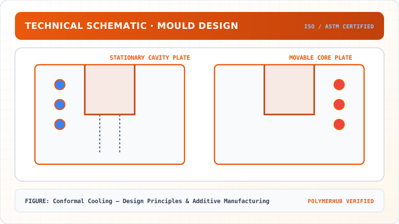
Conformal Cooling — Design Principles & Additive Manufacturing — CAD Tooling & Machine Geometry Blueprint
Critical Geometric Dimensions & Tolerances (GD&T)
- Primary Processing Tolerance:± 0.02 mm (ISO 20457 Class M1)
- Thermal Expansion Allowance:1.5% (Volumetric Shrinkage)
- Draft Angle Minimum:1.0° - 1.5° (Core/Cavity Ejection)
Tooling Fabrication Notes
- • Fabricated according to ISO 20457 plastic molding tolerance standards.
- • EDM finish SPI C-1 applied across cavity optical contact faces.
- • Conformal cooling lines pressure tested at 12 bar water flow.
The Indian polymer processing industry is one of the fastest-growing globally, driven by sectors like automotive, packaging, construction, medical devices, and electrical & electronics. This growth necessitates continuous innovation in manufacturing techniques to enhance efficiency, reduce costs, and improve product quality to meet global standards. Conformal cooling, powered by additive manufacturing, offers a substantial competitive edge for Indian manufacturers.
-
CIPET (Central Institute of Petrochemicals Engineering & Technology): As a premier institution under the Ministry of Chemicals and Fertilizers, CIPET plays a vital role in human resource development and technical support for the plastics industry. Its advanced training centers and research facilities are increasingly incorporating modules on advanced mold design, including conformal cooling and additive manufacturing, to upskill the workforce and prepare them for future manufacturing challenges. Collaborations with industry to demonstrate the benefits of AM for molds are crucial.
-
Automotive Sector: Major automotive OEMs and their Tier-1 suppliers in India (e.g., Maruti Suzuki, Tata Motors, Mahindra, Minda, Motherson Sumi) demand high-quality, lightweight polymer components produced at high volumes. Conformal cooling directly addresses their need for faster cycle times, reduced warpage (critical for aesthetics and fitment), and improved dimensional stability in complex parts like dashboards, bumper fascias, and interior trims. Pune, Chennai, and Manesar are key automotive hubs where adoption is gaining traction.
-
Packaging Industry: India's packaging sector is booming. Companies like Supreme Industries and Finolex Industries are constantly seeking ways to produce packaging solutions more efficiently. For high-volume items, even a small reduction in cycle time per part translates into massive savings annually. Conformal cooling can enhance productivity for thin-wall packaging and containers, where cooling is the dominant cycle phase.
-
Tooling Industry & MSMEs: The mold and die making sector in India, largely comprising Micro, Small, and Medium Enterprises (MSMEs), is gradually exploring and adopting AM technologies. While initial investment is high, government initiatives like the 'Make in India' program and subsidies for advanced manufacturing are encouraging this transition. Specialized tool rooms in clusters like Mumbai, Pune, Gujarat (Silvassa, Daman), and Chennai are the early adopters, using AM to produce complex mold inserts for high-value applications.
-
Government Standards & Initiatives: The Bureau of Indian Standards (BIS) continually updates standards relevant to polymer materials and processing. While specific BIS standards for conformal cooling design are still evolving, the push for energy efficiency and quality control aligns perfectly with the benefits of this technology. Furthermore, the National Manufacturing Policy and policies promoting local manufacturing of high-tech capital goods implicitly support the adoption of advanced tooling techniques.
6. Standard Operating Procedures & Standards
The implementation of conformal cooling involves both mold design principles and additive manufacturing processes. Several international and national standards are relevant:
- ISO 20436: Injection moulds — Requirements for cooling channels: While this standard provides general guidelines for cooling channel design in injection molds, the principles of flow rate, pressure drop, and thermal efficiency remain applicable even for the complex geometries of conformal channels. It serves as a foundational understanding.
- ASTM F2924 / ISO/ASTM 52911: Standard Specification for Additive Manufacturing Titanium-6 Aluminum-4 Vanadium (UNS R56400) with Powder Bed Fusion for Surgical Implant Applications: While specific to titanium for medical implants, this standard (and similar ones for other alloys) is crucial for understanding the general requirements for powder bed fusion (like DMLS/SLM) processes, including material properties, quality control, and post-processing, which are directly transferable to mold steel AM.
- ISO/ASTM 52900: Additive manufacturing — General principles — Fundamentals and vocabulary: Provides a foundational understanding of AM terminology and process classifications, essential for communicating and documenting AM procedures.
- ISO/ASTM 52901: Additive manufacturing — General principles — Material extrusion — Process characteristics and performance: While focused on material extrusion, it highlights the need for standards governing process parameters and material performance in AM, a concept applicable to DMLS.
- VDI 3400: Reference Surfaces for Mold-Making: While not directly for cooling, this German standard (often adopted internationally) defines surface finishes for mold cavities, which are critical for part quality. Achieving such finishes after incorporating conformal cooling often requires careful post-processing (e.g., machining, polishing) of the AM-produced mold insert.
- ISO 16949: Quality management systems — Requirements for automotive production and relevant service parts organizations: For mold makers supplying to the automotive sector, adherence to ISO/TS 16949 (now part of IATF 16949) mandates robust design and manufacturing processes, including validation of cooling efficiency, which conformal cooling significantly enhances.
- BIS (Bureau of Indian Standards): While specific BIS standards for conformal cooling or DMLS for tooling are under development or are adaptations of international norms, relevant BIS standards for tool steels (e.g., BIS 1570, BIS 3749) and for dimensional tolerances of molded parts (e.g., BIS 2102) would apply to the final mold and product.
Standard Operating Procedures (SOPs) for conformal cooling would typically involve:
- Topology Optimization & Design: Using CAE tools (e.g., mold flow analysis, FEA) to optimize channel layout for uniform cooling and minimal pressure drop.
- AM Build Preparation: Slicing CAD model, orienting part, designing support structures, and selecting AM process parameters.
- DMLS/SLM Build Process: Monitoring parameters (laser power, scan speed, layer thickness, atmospheric control).
- Post-Processing: Support removal, heat treatment (stress relief, hardening, tempering), surface finishing, and potentially machining critical features.
- Quality Control: Dimensional inspection (CT scanning for internal channels), material property verification, flow testing, and leak testing of cooling circuits.
7. Key Takeaways & Glossary
Key Takeaways
- Enhanced Thermal Management: Conformal cooling provides superior heat removal compared to conventional cooling, achieving more uniform mold temperatures and eliminating hot spots by closely following the part's geometry.
- Additive Manufacturing as an Enabler: Direct Metal Laser Sintering (DMLS) or Selective Laser Melting (SLM) are indispensable technologies for fabricating the intricate and complex internal geometries of conformal cooling channels in mold inserts.
- Significant Performance Improvements: Implementing conformal cooling leads to substantial benefits, including reduced cycle times (often 15-50%), improved part quality (less warpage, better dimensional stability, enhanced surface finish), and greater energy efficiency in polymer processing operations.
Glossary
- Conformal Cooling: Cooling channels integrated into a mold that precisely follow the contours of the mold cavity, maximizing heat transfer efficiency and promoting uniform temperature distribution throughout the molded part.
- Direct Metal Laser Sintering (DMLS): An additive manufacturing process that uses a high-powered laser to selectively melt and fuse metallic powder particles layer-by-layer, building three-dimensional objects with complex geometries, commonly used for conformal cooling channels.
- Hot Spot: An area within a molded plastic part or mold cavity that cools significantly slower than surrounding regions, leading to localized defects such as sink marks, increased shrinkage, warpage, or longer overall cycle times.
8. Exam & Interview Practice Questions
1. GATE-style Multiple Choice Question
Which of the following is NOT a primary advantage of employing conformal cooling channels in injection molding?
A) Significant reduction in cooling cycle time. B) Improved dimensional stability and reduced warpage of molded parts. C) Elimination of hot spots and more uniform temperature distribution. D) Elimination of the need for mold maintenance and cleaning.
Correct Answer: D Explanation: While conformal cooling improves part quality and reduces cycle times, it does not eliminate the need for routine mold maintenance and cleaning. Molds, regardless of cooling method, still require upkeep for optimal performance and longevity.
2. Numerical Question with Step-by-Step Solution
A polymer part with a maximum wall thickness of needs to be cooled. The polymer has a density , specific heat capacity , and thermal conductivity . The polymer melt temperature is , and the desired ejection temperature is . For conventional cooling, the average mold surface temperature is . For conformal cooling, the average mold surface temperature can be reduced to . Assuming the simplified cooling time model for a semi-infinite slab, calculate the percentage reduction in cooling time achieved by using conformal cooling.
Solution Step:
Solution:
Step 1: Calculate the thermal diffusivity of the polymer (). The formula for thermal diffusivity is . Given: , , .
Step 2: Calculate the cooling time for conventional cooling (). The simplified cooling time equation is . Given: , , , , .
First, calculate the constant term:
Next, calculate the term inside the logarithm for conventional cooling:
Now, calculate :
Step 3: Calculate the cooling time for conformal cooling (). Given: . All other parameters remain the same.
The constant term remains .
Next, calculate the term inside the logarithm for conformal cooling:
Now, calculate :
Step 4: Calculate the percentage reduction in cooling time.
Answer: The use of conformal cooling leads to a 34.51% reduction in cooling time for the polymer part.
3. Conceptual University Exam Question
Discuss the engineering challenges and design considerations associated with implementing conformal cooling channels in injection molds using Direct Metal Laser Sintering (DMLS). Elaborate on how these challenges are addressed to ensure optimal mold performance and longevity.
Solution Step:
Solution:
Implementing conformal cooling via DMLS presents several engineering challenges that require careful consideration during design and manufacturing to achieve optimal mold performance and longevity.
Engineering Challenges:
- Design Complexity & Optimization: Designing intricate 3D channel networks that precisely follow the mold contour while maintaining structural integrity and uniform flow distribution is complex. Traditional CAD software may not be sufficient for topological optimization of cooling paths.
- Material Properties & Anisotropy: DMLS-produced parts can exhibit different mechanical and thermal properties compared to conventionally machined bulk materials due to the layer-by-layer building process, grain structure, and residual stresses. Anisotropy can affect thermal conductivity and wear resistance.
- Surface Finish & Internal Roughness: The as-built surface finish of DMLS channels is typically rougher than conventionally drilled channels. This internal roughness can increase pressure drop, promote fouling, and hinder heat transfer efficiency.
- Porosity & Defects: DMLS parts can suffer from internal porosity, unfused powder, or micro-cracks if process parameters are not optimized. These defects can compromise the mold's structural integrity, lead to leaks, or reduce thermal performance.
- Cost & Lead Time: While DMLS offers design freedom, the material costs (metal powder) and machine time can be higher than conventional machining for simple mold geometries. Post-processing steps further add to the cost and lead time.
- Post-Processing Requirements: DMLS-built inserts typically require extensive post-processing, including support structure removal, heat treatment (stress relief, hardening, tempering), and surface finishing/polishing of the cavity side. Internal channel finishing is particularly difficult.
- Pressure Drop & Flow Uniformity: The complex geometry of conformal channels can lead to high pressure drops and uneven flow distribution if not designed correctly, potentially negating the benefits of proximity to the mold surface.
Addressing Challenges for Optimal Performance and Longevity:
-
Advanced Design & Simulation Tools:
- CAE (Computer-Aided Engineering) Software: Utilizing mold flow analysis (e.g., Moldex3D, Autodesk Moldflow) for thermal and flow simulation is crucial. This helps optimize channel diameter, spacing, and flow path to ensure uniform cooling, minimize hot spots, and predict pressure drop.
- Topology Optimization Algorithms: Specialized software can generate optimal cooling channel layouts based on heat flux maps, maximizing cooling efficiency while respecting manufacturing constraints.
- Generative Design: AI-driven generative design tools can explore a vast design space to propose highly efficient cooling channel geometries.
-
Material Selection & Process Parameter Optimization:
- Specialized AM Alloys: Using high-performance tool steels (e.g., Maraging steels like 1.2709, or modified H13) specifically formulated for DMLS, offering a balance of strength, hardness, and thermal conductivity.
- Process Parameter Development: Meticulous optimization of laser power, scan speed, layer thickness, and hatch spacing to achieve high density, minimal porosity, and desired mechanical properties. This ensures metallurgical integrity and minimizes anisotropic effects.
-
Post-Processing Techniques:
- Hot Isostatic Pressing (HIP): Often employed to eliminate internal porosity, improving density, mechanical properties, and leak resistance, crucial for the longevity of pressurized cooling channels.
- Chemical/Electrochemical Polishing & Abrasive Flow Machining (AFM): While challenging for internal channels, these techniques can improve the internal surface finish, reducing friction, pressure drop, and the risk of fouling.
- Precision Machining & Grinding: Critical external features and mating surfaces are machined to high precision after DMLS to ensure proper mold assembly and functionality.
- Heat Treatment: Essential for achieving the desired hardness, strength, and wear resistance of the mold steel, crucial for extended mold life.
-
Quality Control and Validation:
- Non-Destructive Testing (NDT): Techniques like industrial CT scanning are indispensable for inspecting internal channel integrity, detecting porosity, and verifying dimensional accuracy of complex internal features without destroying the part.
- Flow and Leak Testing: Each conformal cooling circuit must be rigorously tested for proper flow rate, pressure drop, and leak-tightness before mold assembly.
- Mold Performance Trials: Extensive trials with actual polymer materials are conducted to validate predicted cooling performance, cycle time reduction, and part quality.
By systematically addressing these challenges through advanced design, optimized AM processes, and rigorous post-processing and quality control, polymer engineers can leverage conformal cooling to unlock significant improvements in injection molding efficiency, part quality, and overall manufacturing competitiveness.
Conformal Cooling — Design Principles & Additive Manufacturing · Engineering Triad
Material Synthesis · Processing Hardware · Commercial Application
Polycarbonate (PC) Optical Grade
—[O—C₆H₄—C(CH₃)₂—C₆H₄—O—CO]ₙ— (Bisphenol A Polycarbonate)
250-Ton Precision Servo-Hydraulic Moulding Machine
Optics-Calibrated Injection Compression Unit
Automotive Headlamp Lenses & Safety Visors
Impact-resistant optical enclosures with UV-stabilized coating
Test Your Conceptual Understanding
In polymer science and processing thermodynamics, which factor most directly controls the critical transition temperature?
- Always evaluate molecular weight distribution (MWD) alongside zero-shear viscosity when calculating mold shear rates.
- Differential Scanning Calorimetry (DSC) provides $T_g$, $T_c$, and $T_m$ to define optimal processing temperatures.
- Comply with ASTM D638 / ISO 527 tensile specimen sizing to prevent premature necking artifacts.
Personal Lesson Notes
Please sign in to write and save notes during lessons