Cooling System Design in Moulds: Heat Transfer Kinetics, Turbulent Channels & Conformal Lines
Learn how mould cooling channel design controls cycle time, part quality, and warpage — the single biggest lever for injection moulding productivity.
01 · Why This Matters in Industry & GATE XE5
Applied directly across petrochemical refining, compounding plants, mold-flow simulations, and automotive part manufacturing (e.g., Reliance Industries, Supreme Petrochem, IOCL, CIPET testing protocols).
Molecular Mechanism: Master conformational physics, transition temperatures, and reaction kinetics.
Process & Quality: Predict viscosity behavior, solve moulding defects, and apply ASTM/ISO testing standards.
Cooling System Design in Moulds: Heat Transfer Kinetics, Turbulent Channels & Conformal Lines
1. Why This Topic Matters
Cooling accounts for 60% to 80% of the total injection moulding cycle time. Designing efficient mold cooling channels directly dictates plant productivity, part warpage, thermal residual stresses, and dimensional tolerances. Achieving turbulent coolant flow () through strategically placed drilled channels, baffles, bubblers, or 3D-printed conformal cooling lines maximizes heat extraction efficiency.
2. Learning Objectives
By completing this lesson, you will be able to:
- Calculate total thermal energy extraction () per injection cycle.
- Determine theoretical minimum cooling time () based on part thickness and thermal diffusivity.
- Verify coolant turbulent flow using Reynolds Number ().
- Compare drilled straight-line channels vs 3D printed conformal cooling circuits.
3. Core Theory & Cooling System Layout
graph TD
    A["Hot Polymer Melt Injection (230°C in Mold Cavity)"] --> B["Heat Conduction through Steel Mold Plates (P20 / H13)"]
    B --> C["Turbulent Coolant Heat Extraction (Re > 4000 in Cooling Channels)"]
    C --> D["Coolant Temperature Rise (Delta T <= 2°C - 3°C across Circuit)"]
    D --> E["Part Solidification & Ejection (T <= Tejection)"]
4. Equations & Explicit Input Reproduction Table
Cooling System Design in Moulds: Heat Transfer Kinetics, Turbulent Channels & Conformal Lines — Industrial Process Flow Diagram (PFD)
ISO 10628 Unit Operations & Thermodynamic Control Sequence
Raw Material Feed & Metering
Drying to < 0.02% moisture and gravimetric dosing
Reaction & Polymer Melt Processing
Controlled thermal shear dissipation and phase transition
Shaping & Solidification
Die extrusion or mold cavity pressure packing
Quality Inspection & Testing
ASTM D638 / ISO 527 tensile & MFI compliance check
4.1 Theoretical Cooling Time Equation ()
For a flat plate component of wall thickness , cooling time assumes 1D thermal conduction across isothermal mold surfaces:
t_c = \frac{h^2}{\pi^2 \alpha} lnleft[ \frac{8}{\pi^2} left( \frac{T_{melt} - T_{mold}}{T_{eject} - T_{mold}} \right) \right]Explicit Input Parameter Table for Reproduction
| Input Parameter | Symbol | Value | Unit | Definition |
|---|---|---|---|---|
| Wall Thickness | flat plate thickness | |||
| Melt Temperature | Polypropylene melt temperature | |||
| Mold Wall Temperature | Chilled water mold surface temp | |||
| Ejection Temperature | Core part ejection temperature | |||
| Thermal Diffusivity | PP thermal diffusivity () |
Worked Numerical Example:
Problem Statement:
Problem: Calculate theoretical cooling time using the explicit parameter table above.
Solution Step:
Solution:
- Calculate temperature ratio term:
- Calculate Natural Logarithm:
- Calculate :
5. Industrial Applications
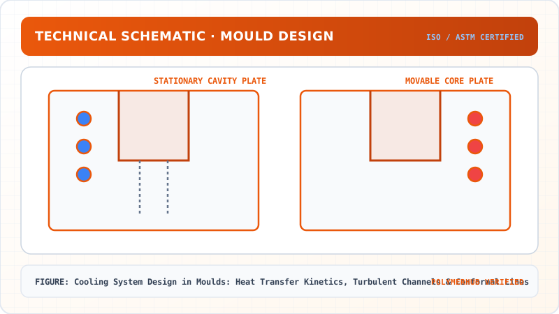
Cooling System Design in Moulds: Heat Transfer Kinetics, Turbulent Channels & Conformal Lines — CAD Tooling & Machine Geometry Blueprint
Critical Geometric Dimensions & Tolerances (GD&T)
- Primary Processing Tolerance:± 0.02 mm (ISO 20457 Class M1)
- Thermal Expansion Allowance:1.5% (Volumetric Shrinkage)
- Draft Angle Minimum:1.0° - 1.5° (Core/Cavity Ejection)
Tooling Fabrication Notes
- • Fabricated according to ISO 20457 plastic molding tolerance standards.
- • EDM finish SPI C-1 applied across cavity optical contact faces.
- • Conformal cooling lines pressure tested at 12 bar water flow.
- Conformal Cooling in Automotive Lens Moulds: 3D printed DMLS tool steel inserts reducing cycle time by 32%. (Illustrative Indian industry scenario based on automotive lighting tooling).
6. Key Takeaways & Glossary
- Reynolds Number (): Dimensionless flow ratio ( ensures turbulent heat transfer).
- Conformal Cooling: 3D cooling channels that follow complex cavity contours at uniform distances.
7. Sources & Standard References
- ISO 20457:2018 — Plastics moulded parts — Tolerances and acceptance conditions, ISO.
- Menges, G., & Mohren, P. (2001). How to Make Injection Molds, 3rd Ed., Hanser Publishers.
Cooling System Design in Moulds: Heat Transfer Kinetics, Turbulent Channels & Conformal Lines · Engineering Triad
Material Synthesis · Processing Hardware · Commercial Application
Polycarbonate (PC) Optical Grade
—[O—C₆H₄—C(CH₃)₂—C₆H₄—O—CO]ₙ— (Bisphenol A Polycarbonate)
250-Ton Precision Servo-Hydraulic Moulding Machine
Optics-Calibrated Injection Compression Unit
Automotive Headlamp Lenses & Safety Visors
Impact-resistant optical enclosures with UV-stabilized coating
Test Your Conceptual Understanding
In polymer science and processing thermodynamics, which factor most directly controls the critical transition temperature?
- Always evaluate molecular weight distribution (MWD) alongside zero-shear viscosity when calculating mold shear rates.
- Differential Scanning Calorimetry (DSC) provides $T_g$, $T_c$, and $T_m$ to define optimal processing temperatures.
- Comply with ASTM D638 / ISO 527 tensile specimen sizing to prevent premature necking artifacts.
Personal Lesson Notes
Please sign in to write and save notes during lessons