Multi-Cavity Runner Balancing: Pressure Drop Equations, Rheological Balancing & Sequential Gating
Multi-cavity runner hydraulic pressure drop modeling via Hagen-Poiseuille, progressive branch sizing, shear-induced thermal runner imbalances, and MeltFlipper solutions.
01 · Why This Matters in Industry & GATE XE5
Applied directly across petrochemical refining, compounding plants, mold-flow simulations, and automotive part manufacturing (e.g., Reliance Industries, Supreme Petrochem, IOCL, CIPET testing protocols).
Molecular Mechanism: Master conformational physics, transition temperatures, and reaction kinetics.
Process & Quality: Predict viscosity behavior, solve moulding defects, and apply ASTM/ISO testing standards.
Multi-Cavity Runner Balancing: Pressure Drop Equations, Rheological Balancing & Sequential Gating
1. Why This Topic Matters
In multi-cavity injection moulds, unbalanced cavity fill causes dimensional variation, short shots in some cavities, flash in others, and unpredictable material properties — all directly affecting part rejection rates. Runner balancing is a critical mould design skill for toolmakers at Rico Auto (Gurugram), Motherson Die Casting (Manesar), and Sundaram-Clayton (Chennai). Understanding pressure drop equations, rheological runner balancing, and sequential valve gating enables zero-reject multi-cavity production.
2. Learning Objectives
- Apply Hagen-Poiseuille equation for runner pressure drop calculation.
- Distinguish geometric (natural/artificial) balancing and rheological balancing.
- Calculate runner diameter for balanced fill using pressure-drop equality.
- Explain the Melt Flipper™ concept and D-shaped runner cross-sections.
- Design sequential valve gating strategy for elimination of weld lines.
3. Core Theory
3.1 Runner Pressure Drop — Hagen-Poiseuille (Power-Law)
For a power-law polymer melt in a circular runner of radius R and length L:
For balanced fill: ΔP must be equal for all cavities — the fundamental balancing criterion.
3.2 Geometric (Naturally Balanced) Runner — H-Pattern
In an H-tree (naturally balanced) runner, all flow paths from sprue to gate are geometrically identical (equal length and diameter). This ensures ΔP_cavity1 = ΔP_cavity2 = ... = ΔP_cavityN at any flow rate.
Limitation: Natural balance only works if all channels have exactly the same shear and thermal history. In practice, curved runners create shear-stratified melt — the hot shear-thinned layer biases to the inner radius, causing melt imbalance even in geometrically symmetric runners.
3.3 Rheological Imbalance and the Melt Flipper™
In a runner bend, low-viscosity hot-core melt migrates to the inner bend. When this runner feeds sub-runners, the hot fraction biases to specific cavities — causing over-fill/under-fill patterns even in geometrically balanced H-runners.
Melt Flipper™ solution: A D-shaped runner cross-section rotates the melt 90° — remixing the shear-stratified layers before the branch, ensuring uniform temperature and viscosity distribution to all cavities.
3.4 Artificial Balancing — Diameter Adjustment
For non-symmetric (family) moulds with cavities of different volume, adjust runner diameter to equalise ΔP:
From Hagen-Poiseuille (Newtonian approximation for runner sizing):
Or more practically, for power-law fluid, runner diameter scales as:
3.5 Sequential Valve Gating
Sequential valve gating (SVG) uses pneumatic/hydraulic valve pins to open gates in sequence:
- Gate 1 opens first → fills centre of part
- Gate 2 opens when melt front from Gate 1 reaches Gate 2 location
- This eliminates weld lines by merging flow fronts while they are still hot
- Used for large automotive panels (bumpers, door trims) and long thin-wall parts
4. Worked Example
Multi-Cavity Runner Balancing: Pressure Drop Equations, Rheological Balancing & Sequential Gating — Industrial Process Flow Diagram (PFD)
ISO 10628 Unit Operations & Thermodynamic Control Sequence
Raw Material Feed & Metering
Drying to < 0.02% moisture and gravimetric dosing
Reaction & Polymer Melt Processing
Controlled thermal shear dissipation and phase transition
Shaping & Solidification
Die extrusion or mold cavity pressure packing
Quality Inspection & Testing
ASTM D638 / ISO 527 tensile & MFI compliance check
Problem Statement:
Problem: A 4-cavity naturally balanced mould has runner length L = 80 mm, runner diameter D = 6 mm, n = 0.35, K = 8000 Pa·sⁿ. Q per cavity = 4×10⁻⁶ m³/s. Calculate ΔP per runner segment.
Interpretation: ΔP = 2.51 MPa per runner segment — with 3 runner branches in series, total injection pressure = ~7.5 MPa runner + gate + cavity = realistic for a compact PP part.
5. Indian Industry Context
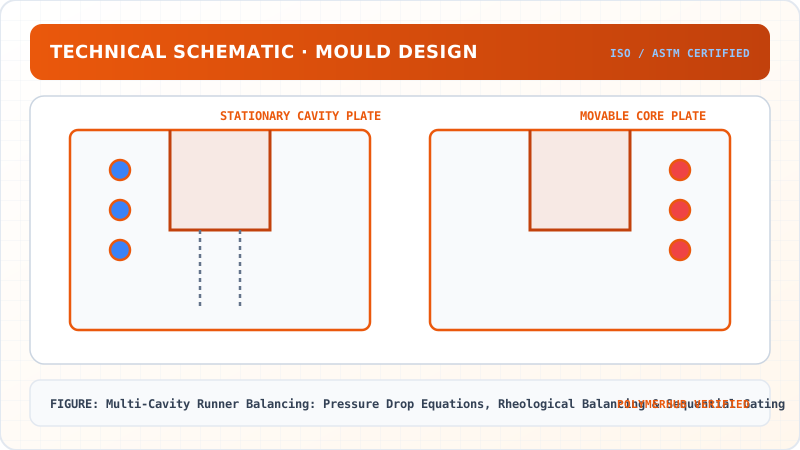
Multi-Cavity Runner Balancing: Pressure Drop Equations, Rheological Balancing & Sequential Gating — CAD Tooling & Machine Geometry Blueprint
Critical Geometric Dimensions & Tolerances (GD&T)
- Primary Processing Tolerance:± 0.02 mm (ISO 20457 Class M1)
- Thermal Expansion Allowance:1.5% (Volumetric Shrinkage)
- Draft Angle Minimum:1.0° - 1.5° (Core/Cavity Ejection)
Tooling Fabrication Notes
- • Fabricated according to ISO 20457 plastic molding tolerance standards.
- • EDM finish SPI C-1 applied across cavity optical contact faces.
- • Conformal cooling lines pressure tested at 12 bar water flow.
Rico Auto Industries (Gurugram) designs and manufactures 16-cavity hot-runner moulds for PP automotive clips. Their mould designers use Moldflow Adviser to verify runner balance (target: ΔP variation between cavities < 5%) and identify shear-stratification imbalance before tool cut.
Sundaram-Clayton (Chennai) uses sequential valve gating on long automotive bumper moulds — 3-gate sequential system eliminates weld lines in PP bumpers for BMW India and Hyundai India, reducing part rejection from 8% (conventional multi-gate) to < 0.5%.
6. Key Takeaways & Glossary
- Hagen-Poiseuille (power-law): ΔP ∝ K·L/R × flow-rate^n — runner pressure drop equation.
- Natural balancing (H-tree): Geometrically identical flow paths — but vulnerable to rheological imbalance.
- Rheological imbalance: Shear-stratified hot melt biases to specific cavities even in geometrically balanced runners.
- Melt Flipper™: D-shaped runner cross-section that rotates melt 90° to re-homogenise shear layers.
- Sequential valve gating (SVG): Gates open in timed sequence — eliminates weld lines in large thin-wall parts.
- Family mould: Mould with cavities of different volumes — requires artificial (diameter) balancing.
7. Standards Reference
- ISO 294-1 — Injection moulding of test specimens
- ASTM D3641 — Injection moulding — Test samples
- SPI/MOLD guidelines — Runner balancing and gate design
8. Practice Questions
- A balanced 8-cavity mould: all runner branches have L = 60 mm, D = 5 mm. If one branch has D = 4 mm due to manufacturing error, calculate the ΔP ratio between D=5 and D=4 runners (Newtonian approximation).
- Explain why a geometrically balanced H-runner can still produce weight variation between cavities.
- What is the advantage of sequential valve gating over simultaneous multi-gating for a 1200 mm automotive bumper?
Multi-Cavity Runner Balancing: Pressure Drop Equations, Rheological Balancing & Sequential Gating · Engineering Triad
Material Synthesis · Processing Hardware · Commercial Application
Polycarbonate (PC) Optical Grade
—[O—C₆H₄—C(CH₃)₂—C₆H₄—O—CO]ₙ— (Bisphenol A Polycarbonate)
250-Ton Precision Servo-Hydraulic Moulding Machine
Optics-Calibrated Injection Compression Unit
Automotive Headlamp Lenses & Safety Visors
Impact-resistant optical enclosures with UV-stabilized coating
Test Your Conceptual Understanding
In polymer science and processing thermodynamics, which factor most directly controls the critical transition temperature?
- Always evaluate molecular weight distribution (MWD) alongside zero-shear viscosity when calculating mold shear rates.
- Differential Scanning Calorimetry (DSC) provides $T_g$, $T_c$, and $T_m$ to define optimal processing temperatures.
- Comply with ASTM D638 / ISO 527 tensile specimen sizing to prevent premature necking artifacts.
Personal Lesson Notes
Please sign in to write and save notes during lessons