Short Fibre Reinforced Thermoplastics: Orientation, Micromechanics & Injection Moulding
Understand the most commercially important composite category by production volume — short glass and carbon fibre reinforced thermoplastics processed by injection moulding — covering compounding, fibre orientation effects, and warpage control.
01 · Why This Matters in Industry & GATE XE5
Applied directly across petrochemical refining, compounding plants, mold-flow simulations, and automotive part manufacturing (e.g., Reliance Industries, Supreme Petrochem, IOCL, CIPET testing protocols).
Molecular Mechanism: Master conformational physics, transition temperatures, and reaction kinetics.
Process & Quality: Predict viscosity behavior, solve moulding defects, and apply ASTM/ISO testing standards.
Short Fibre Reinforced Thermoplastics: Orientation, Micromechanics & Injection Moulding
1. Why This Topic Matters
Short glass fibre reinforced thermoplastics (SFRTs) — especially 30% GF-PA66, 30% GF-PBT, and 20% GF-PP — are the backbone of engineering plastics in automotive, electrical, and consumer durable applications. In India, Zytel (DuPont/Kuraray), Ultramid (BASF), and Sabic Noryl are processed by tier-1 auto suppliers like Motherson Sumi, Minda Industries, and Fiem Industries. Understanding fibre orientation, weld-line weakness, and warpage in injection moulded SFRT parts is critical for structural design and process optimisation.
2. Learning Objectives
- Explain how fibre orientation distribution (FOD) develops during injection moulding (shell-core structure).
- Apply modified Rule of Mixtures with fibre efficiency factor for short-fibre composites.
- Calculate weld-line strength reduction factor and its effect on part load rating.
- Distinguish warpage sources: anisotropic shrinkage vs. thermal gradient vs. fibre orientation.
- Identify ASTM D638 Type I and ISO 527-2 specimen types for SFRT testing.
3. Core Theory
3.1 Fibre Orientation in Injection Moulded Parts
During injection moulding of SFRT, fibres orient along the flow direction in the skin layers (shear-dominant) but remain randomly oriented in the core (extensional flow dominant). This creates the shell-core orientation structure:
| Zone | Flow Type | Fibre Orientation |
|---|---|---|
| Outer skin | Fountain flow + high shear | Highly aligned with flow (anisotropic) |
| Sub-skin | Shear-dominated | Moderately aligned |
| Core | Extensional/diverging | Random (isotropic) or transverse |
Consequence: Properties parallel to flow (L direction) >> properties perpendicular to flow (T direction). Warpage occurs because L shrinkage ≠ T shrinkage.
3.2 Modified Rule of Mixtures for Short Fibres
Short fibres cannot transfer full tensile load (unlike continuous fibres). The Krenchel/Halpin-Tsai modified ROM uses an orientation efficiency factor and a length efficiency factor :
| Parameter | Definition | Typical Value (30% GF PA66) |
|---|---|---|
| Fibre orientation efficiency (0=random, 1=perfect) | 0.375 (random 3D) to 0.8 (injection moulded skin) | |
| Fibre length efficiency ( for ) | 0.85–0.95 for typical 200–400 µm glass fibres | |
| E-glass fibre modulus | 72 GPa | |
| Fibre volume fraction | ~0.17 for 30 wt% GF in PA66 |
3.3 Weld-Line Weakness
At weld lines (where two melt fronts meet), fibres align perpendicular to the weld plane — providing almost no reinforcement across the interface. Weld-line tensile strength for 30% GF-PA66 is typically 50–65% of the unwelded strength.
Mitigation strategies: Relocate weld lines away from high-stress regions; increase melt temperature and injection speed to improve knit-line bonding; use sequential valve gating.
3.4 Anisotropic Shrinkage and Warpage
Fibres restrain shrinkage parallel to their axis but not perpendicular. This differential gives:
| Direction | Shrinkage (30% GF-PA66, dry) |
|---|---|
| Flow direction (L) | 0.3–0.5% |
| Transverse direction (T) | 0.8–1.4% |
Flat plates with unbalanced fibre orientation warp towards the surface with fibres oriented transversely.
4. Worked Example
Short Fibre Reinforced Thermoplastics: Orientation, Micromechanics & Injection Moulding — Industrial Process Flow Diagram (PFD)
ISO 10628 Unit Operations & Thermodynamic Control Sequence
Raw Material Feed & Metering
Drying to < 0.02% moisture and gravimetric dosing
Reaction & Polymer Melt Processing
Controlled thermal shear dissipation and phase transition
Shaping & Solidification
Die extrusion or mold cavity pressure packing
Quality Inspection & Testing
ASTM D638 / ISO 527 tensile & MFI compliance check
Problem Statement:
Problem: A 30% GF PA66 injection moulded bracket has measured . Using modified ROM with (partially aligned skin) and , calculate composite modulus. (E-glass = 72 GPa; PA66 matrix = 2.8 GPa)
Solution Step:
Solution:
Comparison: Datasheet value for 30% GF-PA66 (flow direction) ≈ 9–12 GPa — this ROM estimate falls within the expected range for a partially aligned structure.
5. Indian Industry Context
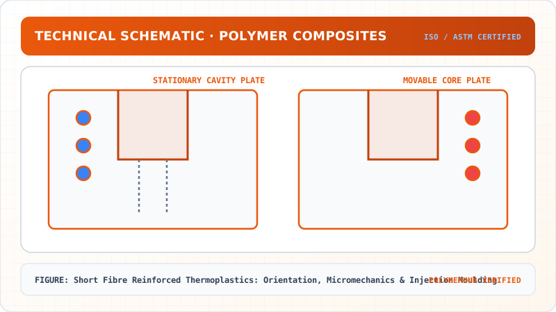
Short Fibre Reinforced Thermoplastics: Orientation, Micromechanics & Injection Moulding — CAD Tooling & Machine Geometry Blueprint
Critical Geometric Dimensions & Tolerances (GD&T)
- Primary Processing Tolerance:± 0.02 mm (ISO 20457 Class M1)
- Thermal Expansion Allowance:1.5% (Volumetric Shrinkage)
- Draft Angle Minimum:1.0° - 1.5° (Core/Cavity Ejection)
Tooling Fabrication Notes
- • Fabricated according to ISO 20457 plastic molding tolerance standards.
- • EDM finish SPI C-1 applied across cavity optical contact faces.
- • Conformal cooling lines pressure tested at 12 bar water flow.
Minda Industries (Noida) moulds 30% GF-PA66 electrical connector housings and 20% GF-PBT relay cases for the Indian automotive market. Their process engineers use Moldflow simulation to predict fibre orientation and identify weld-line positions during tool design phase — before cutting steel — avoiding costly mould rework.
Motherson Sumi Systems (Noida) — India's largest auto component manufacturer — processes GF-PP and GF-PA66 for door panels, sill plates, and under-hood brackets. Weld-line management is a critical quality control issue for load-bearing clips and snap-fit features.
6. Key Takeaways & Glossary
- FOD (Fibre Orientation Distribution): Describes spatial orientation of fibres; measured by microCT or image analysis of polished cross-sections.
- Shell-core structure: Injection moulded SFRT parts have skin fibres aligned with flow, core fibres random.
- (Orientation efficiency): 0.375 for completely random 3D; approaches 1.0 for perfectly aligned.
- (Length efficiency): <1 for short fibres; approaches 1.0 as fibre length >> .
- Weld-line factor: 50–65% strength retention at weld lines for 30% GF thermoplastics.
- Anisotropic shrinkage: Differential L vs T shrinkage due to fibre orientation — primary cause of warpage.
7. Standards Reference
- ASTM D638 Type I — Tensile properties of plastics
- ISO 527-2 — Tensile properties of moulding and extrusion plastics
- ISO 527-4 — Tensile properties of isotropic and orthotropic fibre-reinforced composites
- ASTM D3171 — Constituent content of composite materials
- ISO 294-4 — Shrinkage of injection-moulded thermoplastic specimens
8. GATE / University Practice Questions
- A 20% GF-PP part has , (random), . Calculate (E-glass = 72 GPa, PP = 1.5 GPa).
- Explain why weld-line strength is lower in GF-reinforced plastics than in unfilled polymers.
- What processing change reduces warpage in a thin-wall 30% GF-PA66 lid? Justify using anisotropic shrinkage data.
Short Fibre Reinforced Thermoplastics: Orientation, Micromechanics & Injection Moulding · Engineering Triad
Material Synthesis · Processing Hardware · Commercial Application
Standard Engineering Thermoplastic Resin
—[Monomer Backbone]ₙ— (Calibrated Molecular Weight & PDI)
Industrial Polymer Processing & Tooling System
Computer-Controlled Extrusion / Injection Moulding Hardware
Commercial Engineering Parts & Quality-Inspected Components
Automotive, Electrical, Medical & Packaging Applications
Test Your Conceptual Understanding
In polymer science and processing thermodynamics, which factor most directly controls the critical transition temperature?
- Always evaluate molecular weight distribution (MWD) alongside zero-shear viscosity when calculating mold shear rates.
- Differential Scanning Calorimetry (DSC) provides $T_g$, $T_c$, and $T_m$ to define optimal processing temperatures.
- Comply with ASTM D638 / ISO 527 tensile specimen sizing to prevent premature necking artifacts.
Personal Lesson Notes
Please sign in to write and save notes during lessons