Resin Transfer Moulding (RTM): Darcy Flow, Preform Permeability & Gelation Control
Resin Transfer Moulding (RTM) liquid composite moulding physics, 3D Darcy's Law preform flow, anisotropic permeability tensor K, resin gelation viscosity windows, and vent optimization.
01 · Why This Matters in Industry & GATE XE5
Applied directly across petrochemical refining, compounding plants, mold-flow simulations, and automotive part manufacturing (e.g., Reliance Industries, Supreme Petrochem, IOCL, CIPET testing protocols).
Molecular Mechanism: Master conformational physics, transition temperatures, and reaction kinetics.
Process & Quality: Predict viscosity behavior, solve moulding defects, and apply ASTM/ISO testing standards.
Resin Transfer Moulding (RTM): Darcy Flow, Preform Permeability & Gelation Control
1. Why This Topic Matters
RTM produces net-shape, high-fibre-fraction composite parts in a closed mould — eliminating open-mould VOC emissions and enabling automated, repeatable production. Wind turbine spar caps (Suzlon, Inox Wind), automotive CFRP structural brackets (Tata Advanced Systems), and aerospace composite ribs (HAL) are manufactured by RTM or its variants (VARTM, SCRIMP). Understanding Darcy flow, preform permeability, and gelation window is essential to design RTM tooling and avoid dry spots, voids, or premature gel.
2. Learning Objectives
- Apply Darcy's Law to model resin flow through a textile preform.
- Distinguish in-plane permeability K₁₁ from through-thickness permeability K₃₃.
- Calculate fill time for a given mould geometry, preform permeability, and injection pressure.
- Define and apply the gelation window to set RTM injection temperature and demould time.
- Identify ASTM D5687 and ISO 15472 permeability measurement standards.
3. Core Theory
3.1 Darcy's Law for Resin Flow in a Preform
Resin flow through a fibre preform is governed by Darcy's Law:
Where: u = Darcy velocity (resin superficial velocity, m/s), K = permeability tensor (m²), µ = resin viscosity (Pa·s), ∇P = pressure gradient (Pa/m).
For 1D linear flow in a flat preform of length L:
3.2 Preform Permeability
Permeability K depends on fibre architecture and fibre volume fraction V_f:
Kozeny-Carman equation (approximate):
Where: r_f = fibre radius (m), k_z = Kozeny constant (≈4–6 for aligned fibres), V_f = fibre volume fraction.
| Preform Architecture | K₁₁ (m²) Typical | K₃₃ (m²) Typical |
|---|---|---|
| Woven fabric (Vf = 0.55) | 1×10⁻¹⁰ – 1×10⁻¹¹ | 1×10⁻¹² – 1×10⁻¹³ |
| UD non-crimp fabric | 1×10⁻¹⁰ (parallel) | 1×10⁻¹³ (transverse) |
| Chopped strand mat | 5×10⁻¹⁰ – 5×10⁻¹¹ | Similar (isotropic) |
3.3 Fill Time Calculation (1D Darcy)
For linear mould filling at constant injection pressure ΔP:
Where: φ = preform porosity (= 1 - V_f), L = mould length, K = permeability, µ = resin viscosity, ΔP = injection pressure.
3.4 Gelation Window
The gelation window is the time available for mould filling before the resin gels:
Injection must complete before 70% of gel time (safety factor). Increasing temperature shortens t_gel but reduces µ (lowers fill time) — a critical trade-off.
4. Worked Example
Resin Transfer Moulding (RTM): Darcy Flow, Preform Permeability & Gelation Control — Industrial Process Flow Diagram (PFD)
ISO 10628 Unit Operations & Thermodynamic Control Sequence
Raw Material Feed & Metering
Drying to < 0.02% moisture and gravimetric dosing
Reaction & Polymer Melt Processing
Controlled thermal shear dissipation and phase transition
Shaping & Solidification
Die extrusion or mold cavity pressure packing
Quality Inspection & Testing
ASTM D638 / ISO 527 tensile & MFI compliance check
Problem Statement:
Problem: RTM injection into a 600 mm × 600 mm GFRP preform (V_f = 0.50). K = 3.0×10⁻¹¹ m², resin µ = 0.08 Pa·s, ΔP = 0.5 MPa. Calculate 1D fill time.
Interpretation: 8 minute fill time — well within a typical epoxy gel time of 30–60 min at 60°C injection temperature. If gel time at 80°C is only 15 min, the injection temperature must be reduced or injection pressure increased.
5. Indian Industry Context
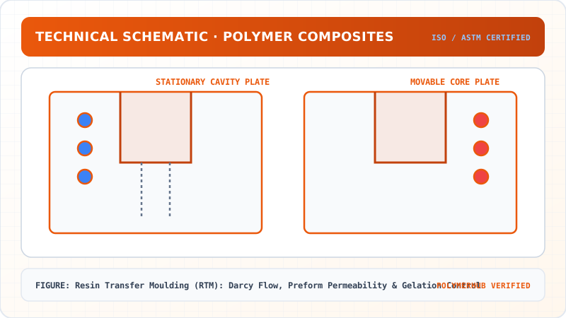
Resin Transfer Moulding (RTM): Darcy Flow, Preform Permeability & Gelation Control — CAD Tooling & Machine Geometry Blueprint
Critical Geometric Dimensions & Tolerances (GD&T)
- Primary Processing Tolerance:± 0.02 mm (ISO 20457 Class M1)
- Thermal Expansion Allowance:1.5% (Volumetric Shrinkage)
- Draft Angle Minimum:1.0° - 1.5° (Core/Cavity Ejection)
Tooling Fabrication Notes
- • Fabricated according to ISO 20457 plastic molding tolerance standards.
- • EDM finish SPI C-1 applied across cavity optical contact faces.
- • Conformal cooling lines pressure tested at 12 bar water flow.
Suzlon Energy (Pune) manufactures 2.1 MW GFRP wind blades using Vacuum Assisted RTM (VARTM) at their Pondicherry factory. The spar cap lay-up uses biaxial NCF fabric with K₁₁ = 2×10⁻¹¹ m². Filling a 45 m blade mould half-shell requires multi-port injection and simulated Darcy flow analysis in PAM-RTM software to prevent dry spots.
Tata Advanced Systems (Hyderabad) produces CFRP composite panels for Airbus A320 family using RTM with high-temperature epoxy (180°C cure). Precise temperature control is critical to manage the gelation window and prevent race-tracking along mould edges.
6. Key Takeaways & Glossary
- Darcy's Law: Resin flow velocity is proportional to permeability and pressure gradient, inversely proportional to viscosity.
- Permeability K: Property of fibre preform architecture; decreases with increasing V_f.
- Gelation window: Time before resin gels — injection must complete within 70% of gel time.
- Kozeny-Carman: Theoretical permeability model relating K to fibre radius, V_f, and Kozeny constant.
- VARTM: Vacuum Assisted RTM — uses atmospheric pressure (0.1 MPa) instead of injection pressure; lower V_f but lower tooling cost.
- Race-tracking: Resin flowing faster along mould edges than through preform — causing dry spots in core.
7. Standards Reference
- ASTM D5687 — Standard Guide for Preparation of Flat Composite Panels with Processing Guidelines
- ISO 15472 — Vacuum Infusion Process for Fabrication of Fibre-Reinforced Polymer Composites
- ASTM D2584 — Ignition Loss of Cured Reinforced Resins (glass content verification)
- ASTM D3171 — Constituent Content of Composite Materials
8. GATE / University Practice Questions
- Calculate fill time for a 1 m × 1 m RTM mould: K = 5×10⁻¹¹ m², µ = 0.12 Pa·s, ΔP = 0.3 MPa, V_f = 0.55.
- Why does increasing injection temperature reduce fill time but also reduce the gelation safety window?
- What is race-tracking in RTM and how does preform edge sealing prevent it?
Resin Transfer Moulding (RTM): Darcy Flow, Preform Permeability & Gelation Control · Engineering Triad
Material Synthesis · Processing Hardware · Commercial Application
Standard Engineering Thermoplastic Resin
—[Monomer Backbone]ₙ— (Calibrated Molecular Weight & PDI)
Industrial Polymer Processing & Tooling System
Computer-Controlled Extrusion / Injection Moulding Hardware
Commercial Engineering Parts & Quality-Inspected Components
Automotive, Electrical, Medical & Packaging Applications
Test Your Conceptual Understanding
In polymer science and processing thermodynamics, which factor most directly controls the critical transition temperature?
- Always evaluate molecular weight distribution (MWD) alongside zero-shear viscosity when calculating mold shear rates.
- Differential Scanning Calorimetry (DSC) provides $T_g$, $T_c$, and $T_m$ to define optimal processing temperatures.
- Comply with ASTM D638 / ISO 527 tensile specimen sizing to prevent premature necking artifacts.
Personal Lesson Notes
Please sign in to write and save notes during lessons